Equipment for excavation of deep boreholes in geological formation and the manner of energy and material transport in the boreholes

a geological formation and deep-bore technology, applied in the direction of well accessories, fluid removal, drilling machines and methods, etc., can solve the problems of high energy demand, inability to achieve substantial saving of drilling, and difficulty in achieving the effect of substantial energy saving and larger boreholes

Inactive Publication Date: 2010-09-09
GA DRILLING AS
View PDF8 Cites 43 Cited by
  • Summary
  • Abstract
  • Description
  • Claims
  • Application Information

AI Technical Summary

Benefits of technology

[0104]As the transport is performed by help of transport module, the rock need not be crushed, but can be in large compact blocks. This implies a significant fact, namely that rock can be separated by cuts with the volume representing only a fraction of the extracted rock; thus, considerable energy saving will result, as well as block shape unification and larger borehole diameter.

Problems solved by technology

Thus, finding a boring technology allowing approximately linear growth of bore price and depth is an imperative challenge.
The system evaporates rock, and thus high energy demand results.
However, none of the above methods was successful in reaching substantial saving during boring, due to simultaneous effect of several factors:
transport of extracted material to the ground remained unsolvedsupply of energyconsiderable energy demand—the need to crush the entire borehole volume to small particles, or even (with laser technologies) to evaporate it.
Effectiveness of the above technologies is also opposed by the presence of liquid (water, viscous transport liquid) in the borehole.
An equally important part of the borehole is casing of its walls by subsequently inserted pipes which, moreover, are narrowing with borehole length, and thus cause overall throughput reduction and contribute to inadequate boring price increase with bore depth.

Method used


Image

  • Equipment for excavation of deep boreholes in geological formation and the manner of energy and material transport in the boreholes
  • Equipment for excavation of deep boreholes in geological formation and the manner of energy and material transport in the boreholes
  • Equipment for excavation of deep boreholes in geological formation and the manner of energy and material transport in the boreholes

Examples


Embodiment Construction

OF EMBODIMENTS

[0117]The figures show the sequence starting with current state-of-the-art and following with some preferable embodiments of the invention.

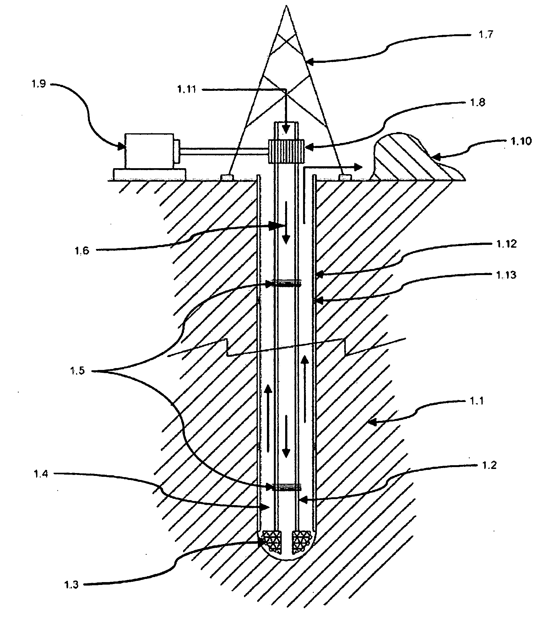
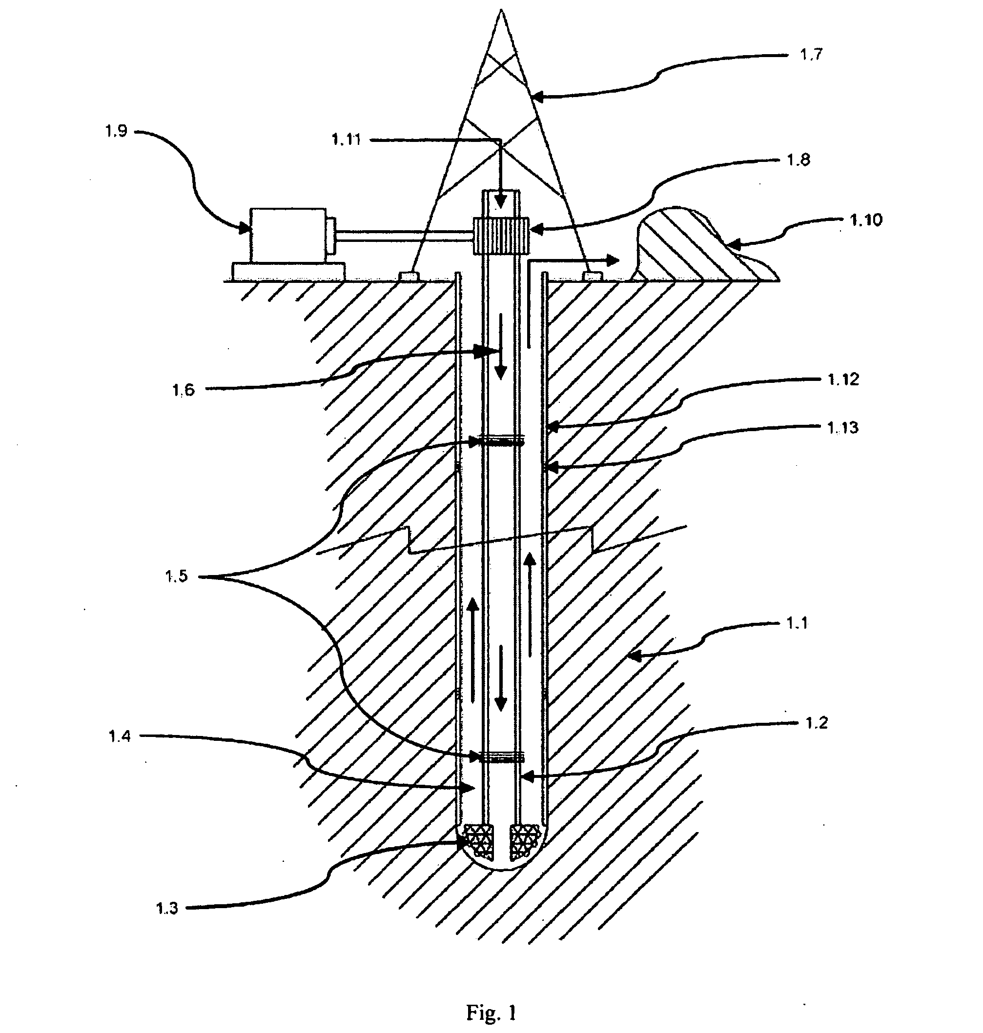
[0118]FIG. 1 shows current state-of-the-art of making a borehole in geological formation.

[0119]In geological formation 1.1 borehole 1.4 is made using torsion piping 1.2, on the bottom end of which drilling head 1.3 is attached equipped with special high resistance teeth through which liquid 1.6 intended for rock flushing flows. The torsion piping consists of several parts and sections connected by joints 1.5, and is being extended in proportion to the borehole depth achieved.

[0120]The torsion piping 1.2 is rotated by drive 1.9 via transmission device 1.8. Liquid (mostly water, but often also highly viscous squash) 1.11 is forced into the torsion piping; the liquid 1.11 transports the borehole material to the surface via the remaining borehole space (flushing), where rock 1.10 is separated and the liquid is collected.

[0121]Casing 1.1...


PUM


Abstract

Utilisation of geothermal energy in depths above 5 km could contribute considerably to resolving the global problems related to a lack of energy and to glasshouse gases from fossil fuels. The invention describes innovative equipment which makes deep holes in geological formations (rock) by disintegrating the soil into blocks carried to the land surface through the excavated hole filled with liquid, using transport modules yielded up by gas buoyancy interaction in the transport module utilising supercavitation. In an opposite direction—by help of negative buoyancy—the necessary energy carriers, materials and components, or entire devices required for rock excavation, are carried to the bottom. The opportunity to transport rock in entire blocks reduces energy consumption considerably, because the rock is disintegrated in the section volumes only. Some of the extracted rock and material carried from the surface is used to make a casing of the hole using a part of the equipment. The equipment also allows the generation of the necessary high pressure of liquid at the bottom of the hole, to increase permeability of adjacent rock. The equipment as a whole allows by its function that there is almost linear dependence between the price and depth (length) of the produced hole (borehole).

Description

BACKGROUND ART[0001]At present, crude oil and gas extraction, and geological or geothermal bores are realised by help of drilling rigs where rock is disintegrated by rotating drilling heads mounted at the end of assemblies of connected basic piping and rotated by driving units on land surface. Disintegrated rock is transported to land surface by help of special liquid circulating in the piping and in the drilled hole. There were efforts to put the driving units close to the drilling head and to bring energy from the land surface, but with transport of the crushed rock in classical manner—by help of highly viscous, quick-circulating liquid.[0002]Primarily during the last decade, new methods of more effective rock disintegration and transport to land surface have been sought for.[0003]In the latest study made at MIT (USA) “THE FUTURE OF GEOTHERMAL ENERGY”—IMPACT OF ENHANCED GEOTHERMAL SYSTEMS (EGS) ON THE UNITED STATES IN THE 21ST CENTURY 2006 the principal importance of resolving an ...

Claims


Application Information

Patent Timeline
Patent Type & Authority Applications(United States)
IPC IPC(8): E21B7/14
CPCE21B7/14
Inventor KOCIS, IVANKRISTOFIC, TOMASKOCIS, IGOR
Owner GA DRILLING AS
Why Eureka
Try Eureka