
Crystal- based oscillator for use in synchronized system

a synchronized system and crystal-based technology, applied in the field of crystal-based oscillators, can solve the problems that the synchronous clock circuit described in the stephens paper, however, will not work with a sxo module of just any design, and achieve the effect of redundancy and scalability

Active Publication Date: 2010-09-09
SYNC N SCALE
View PDF14 Cites 7 Cited by
  • Summary
  • Abstract
  • Description
  • Claims
  • Application Information

AI Technical Summary

Benefits of technology

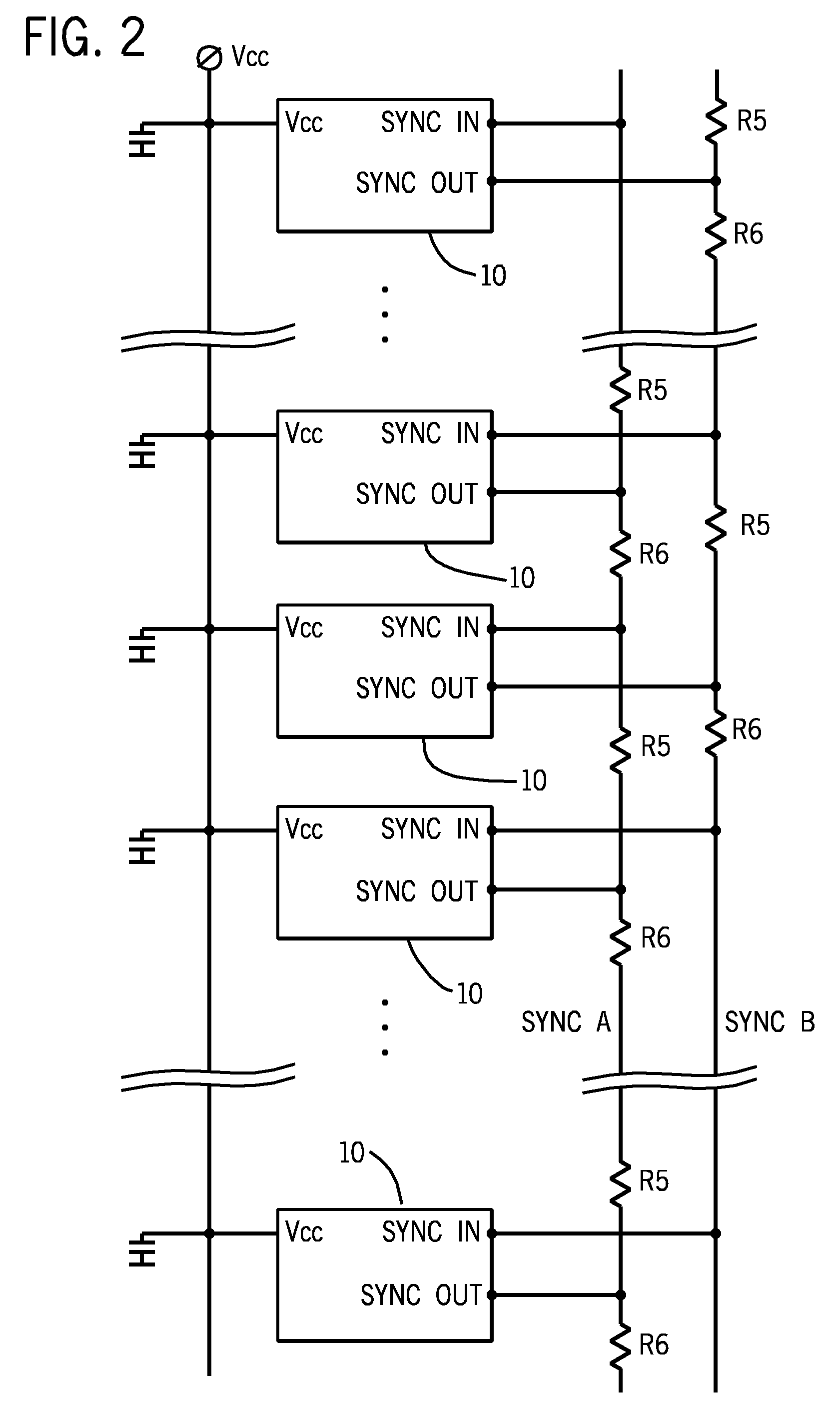
[0012]The synchronous clock circuit described in the Stephens paper, however, will not work with a SXO module of just any design. A need therefore exists to provide a clock synchronization system with many of the benefits of asynchronous structure—including no central clock, no fanout or buffers, no PLLs, and therefore none of problems associated with these extra components—and all of the benefits of synchronous architecture. A need further exists to provide a system that eliminates the possibility of catastrophic central clock failure and provides redundancy and scalability. Finally, a need exists for an SXO module that provides the benefits hoped for in the dual bus system described in the Boroditsky paper.

Problems solved by technology

The synchronous clock circuit described in the Stephens paper, however, will not work with a SXO module of just any design.

Method used


Image

  • Crystal- based oscillator for use in synchronized system
  • Crystal- based oscillator for use in synchronized system
  • Crystal- based oscillator for use in synchronized system

Examples


Embodiment Construction

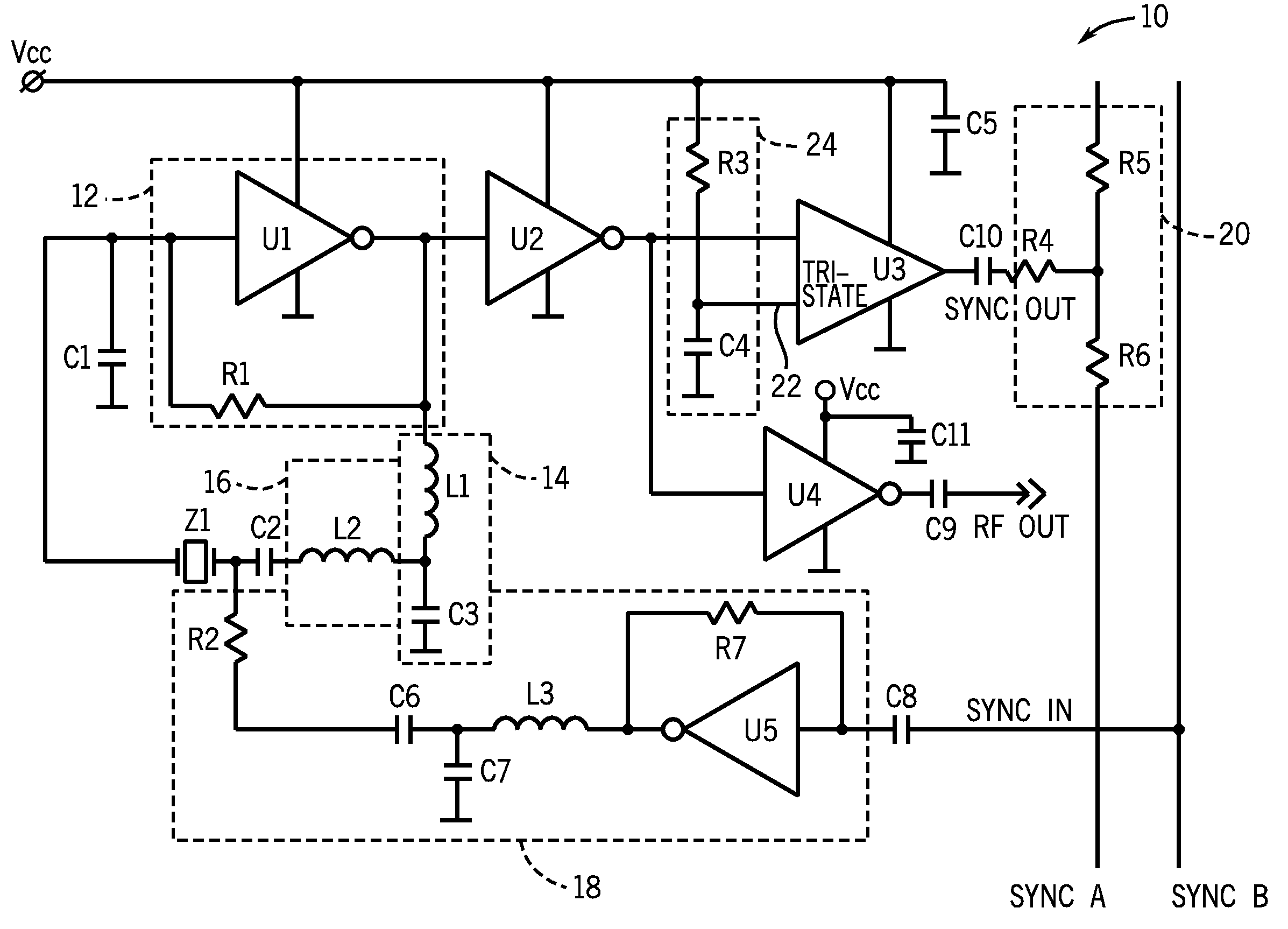
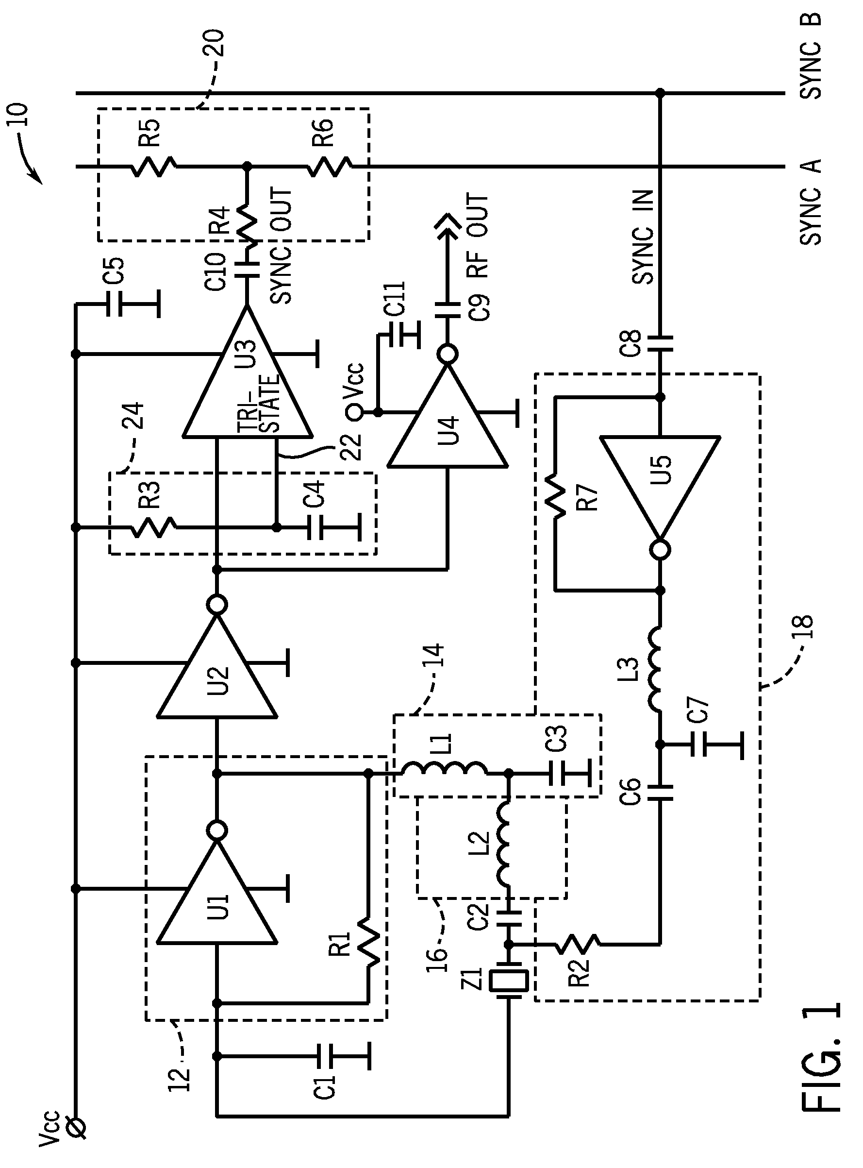
[0017]As shown in FIG. 1, a synchronized crystal oscillator (SXO) module 10 according to a preferred embodiment of the invention includes a sustaining stage amplifier 12, in this case formed by a CMOS inverter gate U1 with a biasing resistor R1, and a phase shifting, gain control network 14, formed by inductor L1 and capacitor C3. Further included is a resonator Z1 (in this case a quartz crystal), connected in series with a synchronization range expansion circuit 16. Circuit 16 allows a significant reduction in the cost of the system and improves phase noise and jitter performance. This goal is achieved by using a higher Q, less pullable and much less expensive overtone crystal resonator in resonator Z1. In the embodiment shown, synchronization range expansion circuit 16 is formed by an inductor L2, connected in series with resonator Z1. Capacitor C1 provides a phase shift function, and capacitor C2 provides a DC blocking function.

[0018]The signal enters the SXO module 10 from the S...


PUM


Abstract

A crystal oscillator-based module, which includes a crystal resonator receiving a conditioned signal from a first bus and passing a resonator signal to a sustaining stage amplifier. A synchronization range expansion circuit is connected between a gain control network and the resonator. A tri-state buffer has a main input connected to receive the resonator signal through a buffer. The output of the tri-state buffer is connected to a second bus, through a matching network if necessary. A synchronous clock system can be formed by connecting these modules alternately to the two busses. The tri-state buffer also has a control input, which may be connected to a delay circuit between Vcc and ground, so as to allow hot swapping and for other benefits.

Description

BACKGROUND OF THE INVENTION[0001]This invention relates to crystal oscillators, and specifically to crystal oscillators for use with other similar crystal oscillators in a synchronized system.[0002]Clock signals are the most important control signals in digital systems. Regardless of the modulation scheme, the timing of logic transitions is dictated by the system's clock. The performance of a system at any level—on a chip, on a board, or across boards—is predicated by the coordination of clock signals among the components. Example known applications can be described as follows.[0003]Synchronous Systems. Synchronous systems provide clock signals that are frequency locked at every transmission / reception exchange and require a design with zero skew to set the phase relationship between signal and clock. Difficulties in coordinating clock signals in synchronous systems differ at the chip, circuit, and system levels. On a chip, a single clock is easily distributed to drive every element ...

Claims


Application Information

Patent Timeline
Patent Type & Authority Applications(United States)
IPC IPC(8): H03L7/00
CPCH03B5/364G06F1/04G06F1/12H03B2200/0074
Inventor BORODITSKY, ROMANGOMEZ, JORGE
Owner SYNC N SCALE
Learn More