Display, timing controller and data driver for transmitting serialized mult-level data signal

Active Publication Date: 2010-09-09
ANAPASS
View PDF14 Cites 54 Cited by
  • Summary
  • Abstract
  • Description
  • Claims
  • Application Information

AI Technical Summary

Benefits of technology

[0011]In addition, as shown in FIG. 4, a configuration wherein a data driver 23 receives a clock signal in a chain form has been recently proposed. Such configuration is advantageous in that an impedance mismatch due to a multi-drop of a clock line and a resulting EMI can be reduced. However, this configuration is problematic that a data sampling is failed due to a delay of a clock occurring between the data driver 23.
[0012]As described above, the latest trend in the intra-panel interface is focused on reducing the number of signal lines and EMI component. In addition, an operating speed and a resolution of a panel are increased compared with the reduction of the number of signal lines so that a novel intra-panel interface that can solve problems such as the skew, the relative jitter and the EMI occurring during a high speed signal transmission process is required.
[0013]It is an object of the present invention to provide a display, a timing controller and a data driver wherein a serialized multi-leve

Problems solved by technology

However, a large amount of an EMI (electromagnetic interference) and an RFI (radio frequency interference) hereinafter commonly referred to as “EMI”) are generated in a line for transmitting a data signal between the timing controller and the data driver.
However, the multi-drop method employed

Method used


Image

  • Display, timing controller and data driver for transmitting serialized mult-level data signal
  • Display, timing controller and data driver for transmitting serialized mult-level data signal
  • Display, timing controller and data driver for transmitting serialized mult-level data signal

Examples


first embodiment

[0036]FIG. 5 is a diagram illustrating a structure of a display in accordance with a first embodiment of the present invention, and FIG. 6 is a diagram illustrating only transmission structures of a clock and a data between a timing controller and data drivers of FIG. 5. Referring to FIGS. 5 and 6, the display comprises a timing controller 14, data drivers 24, scan drivers 30 and a display panel 40.

[0037]The display panel 40 display an image according to scan signals S1 through Sn and data signals D1 through Dm. the display panel 40 may comprise different types of display panels such as an LCD panel, a PDP panel or an OLED panel. The scan drivers 30 apply the scan signals S1 through Sn to the display panel 40, and the data driver 24 apply the data signals D1 through Dm to the display panel 40. The timing controller 14 transmits a data signal DT to the data driver 24, and applies clock signals CLK and CLK_R to the data driver 24 and the scan driver 30.

[0038]The data signal DT transmi...

second embodiment

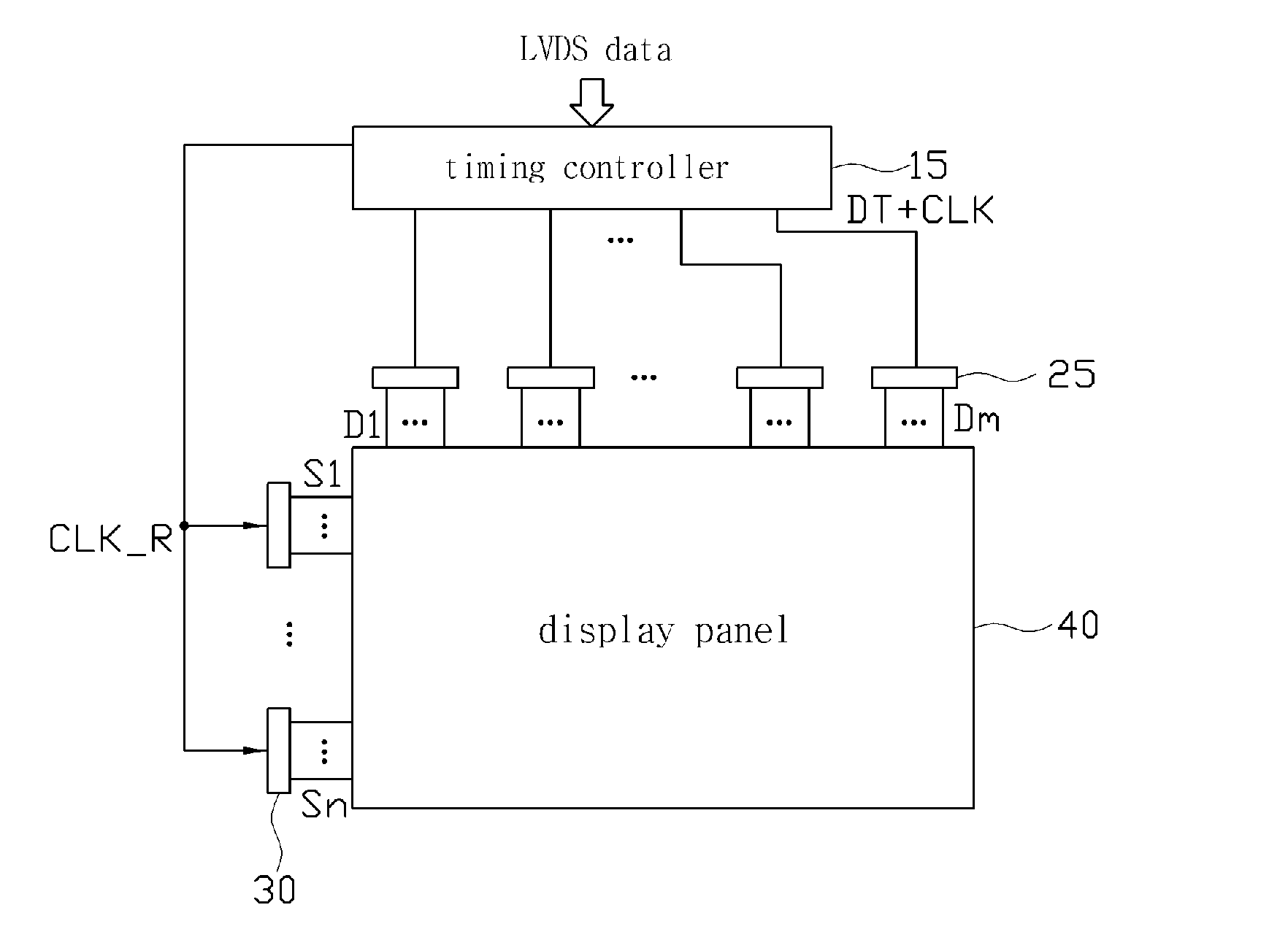
[0056]FIG. 10 is a diagram illustrating a structure of a display in accordance with a second embodiment of the present invention, and FIG. 11 is a diagram illustrating only transmission structures of a clock signal and a data signal between a timing controller and data drivers of FIG. 10. Referring to FIGS. 10 and 11, the display comprises a timing controller 15, data drivers 25, scan drivers 30 and a display panel 40.

[0057]The display in accordance with the second embodiment of the present invention is similar to that of the first embodiment. However, the display in accordance with the second embodiment of the present invention differs from that of the first embodiment in that the clock signal CLK is embedded in the data signal DT to have a level different from that of the data signal. More specifically, the data signal DT may have at least four different levels, and the embedded clock signal has a level different from the levels of the data signal DT. The clock signal CLK may be e...

third embodiment

[0087]FIG. 18 is a diagram illustrating a structure of a display in accordance with a third embodiment of the present invention, and FIG. 19 is a diagram illustrating only transmission structures of a clock signal and a data signal between a timing controller 16 and data drivers 26 of FIG. 18.

[0088]The third embodiment of the present invention employs a point-to-couple scheme while the second embodiment and the third embodiment of the present invention employs the point-to-point scheme. Since the third embodiment of the present invention is basically identical to the second embodiment except that the third embodiment employs the point-to-couple scheme, the multi-level signaling that may be used for an interface between the timing controller and the data driver described with reference to FIGS. 10 through 17 may also be used for the third embodiment. However, while a single transmission signal is transmitted to a single data driver in accordance with the second embodiment, a single t...


PUM


Abstract

The present invention relates to a display, a timing controller and a data driver for transmitting a serialized multi-level data signal, and more particularly to a display, a timing controller and a data driver for transmitting a serialized multi-level data signal for reducing the number of wirings between the timing controller and the data driver, and for reducing an EMI component. The display of the present invention comprises a display panel, a scan driver, a timing controller and a plurality of data drivers, wherein the timing controller transmits a transmission signal including a serialized data signal to one of the plurality of the data drivers, wherein a level of the data signal is selected from at least four different levels according to a value of a data having a length of at least two bits, and wherein the data driver restores the data from the transmitted transmission signal.

Description

TECHNICAL FIELD[0001]The present invention relates to a display, a timing controller and a data driver for transmitting a serialized multi-level data signal, and more particularly to a display, a timing controller and a data driver for transmitting a serialized multi-level data signal for reducing the number of wirings between the timing controller and the data driver, and for reducing an EMI component.BACKGROUND ART[0002]Recently, in addition to an increase in a popularization of portable electronic devices such as a notebook computer and a personal portable communication device, a market size of digital appliances and personal computers is constantly increased. Display apparatuses which are final connection medium between such devices and users is required to have a light weight and low power consumption. Therefore, FPDs (Flat Panel Displays) such as an LCD (Liquid Crystal Display), a PDP (Plasma Display Panel) and an OELD (Organic Electro-Luminescence Display) are generally used ...

Claims


Application Information

Patent Timeline
IPC IPC(8): G09G5/00G09G3/36
CPCG09G3/20H04L25/0272G09G2370/08G09G2330/06
Inventor LEE, YONG-JAE
Owner ANAPASS
Why Eureka
Try Eureka