Shared Isolated Gas Cooling System for Oppositely Facing Electronic Displays

a technology of electronic displays and cooling systems, which is applied in indirect heat exchangers, lighting and heating apparatus, instruments, etc., can solve the problems of insufficient system, inadequate cooling of only the rear interior of the display, and the demands of the market for larger screen sizes for displays, etc., to achieve bright backlights, increase heat production, and large fluctuation of temperature

Active Publication Date: 2010-09-09
MFG RESOURCES INT INC
View PDF33 Cites 84 Cited by
  • Summary
  • Abstract
  • Description
  • Claims
  • Application Information

AI Technical Summary

Benefits of technology

[0005]In the past, many displays have functioned satisfactorily with ten or twelve inch screens. Now, many displays are in need of screens having sizes greater than or equal to twenty-four inches which may require improved cooling systems. For example, some outdoor applications call for seventy-inch screens and above. The dual effect of increased heat production from the larger screens, brighter backlights, and radiative heat transfer from the sun through the display window, make heat dissipation systems of the past, which attempt to cool only the rear interior of the display inadequate.
[0006]When used outdoors, or in warm ambient environments, a large fluctuation in temperature is common in the devices of the past. Such temperature fluctuation adversely affects the electronic components in these devices. Whereas the systems of the past attempted to remove heat only through the non-display sides of the electronic display, a preferred embodiment causes convective heat transfer from the face of the display as well. By the aspects described below, the exemplary embodiments have made consistent cooling possible for electronic displays having screens of sizes greater than twelve inches. For example, cooling of a 55 inch screen or greater can be achieved, even in extremely hot climates and in direct sunlight. Greater cooling capabilities are provided by the device and method described and shown in more detail below.
[0007]There is demand in the market for us...

Problems solved by technology

When used outdoors or in warm ambient conditions, these systems are not adequate, especially when radiative heat transfer from the sun through a display window becomes a major factor.
Furthermore, the market is demanding larger screen sizes for displays.
The dual effect of increased heat production from the larger screens, brighter backligh...

Method used


Image

  • Shared Isolated Gas Cooling System for Oppositely Facing Electronic Displays
  • Shared Isolated Gas Cooling System for Oppositely Facing Electronic Displays
  • Shared Isolated Gas Cooling System for Oppositely Facing Electronic Displays

Examples


Embodiment Construction

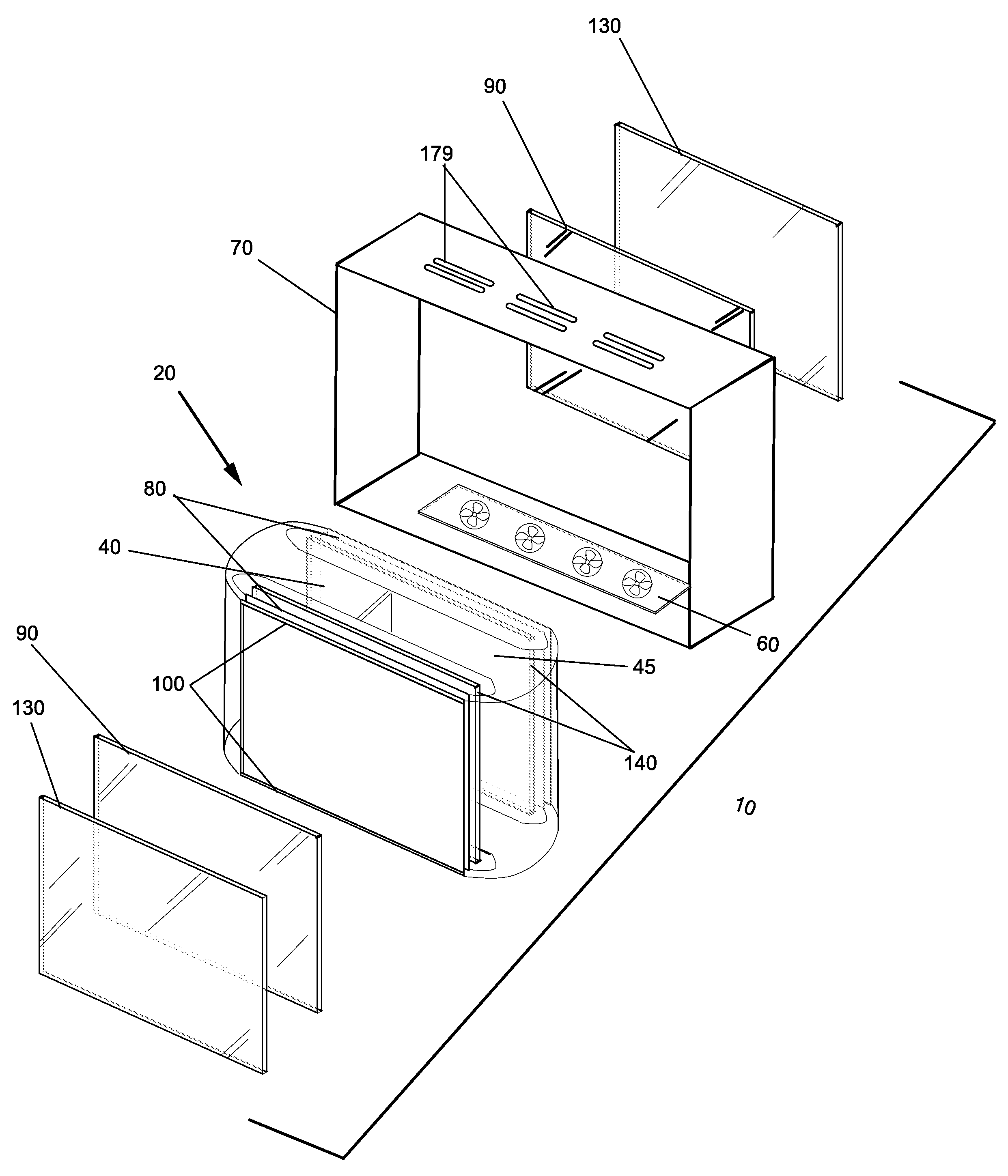
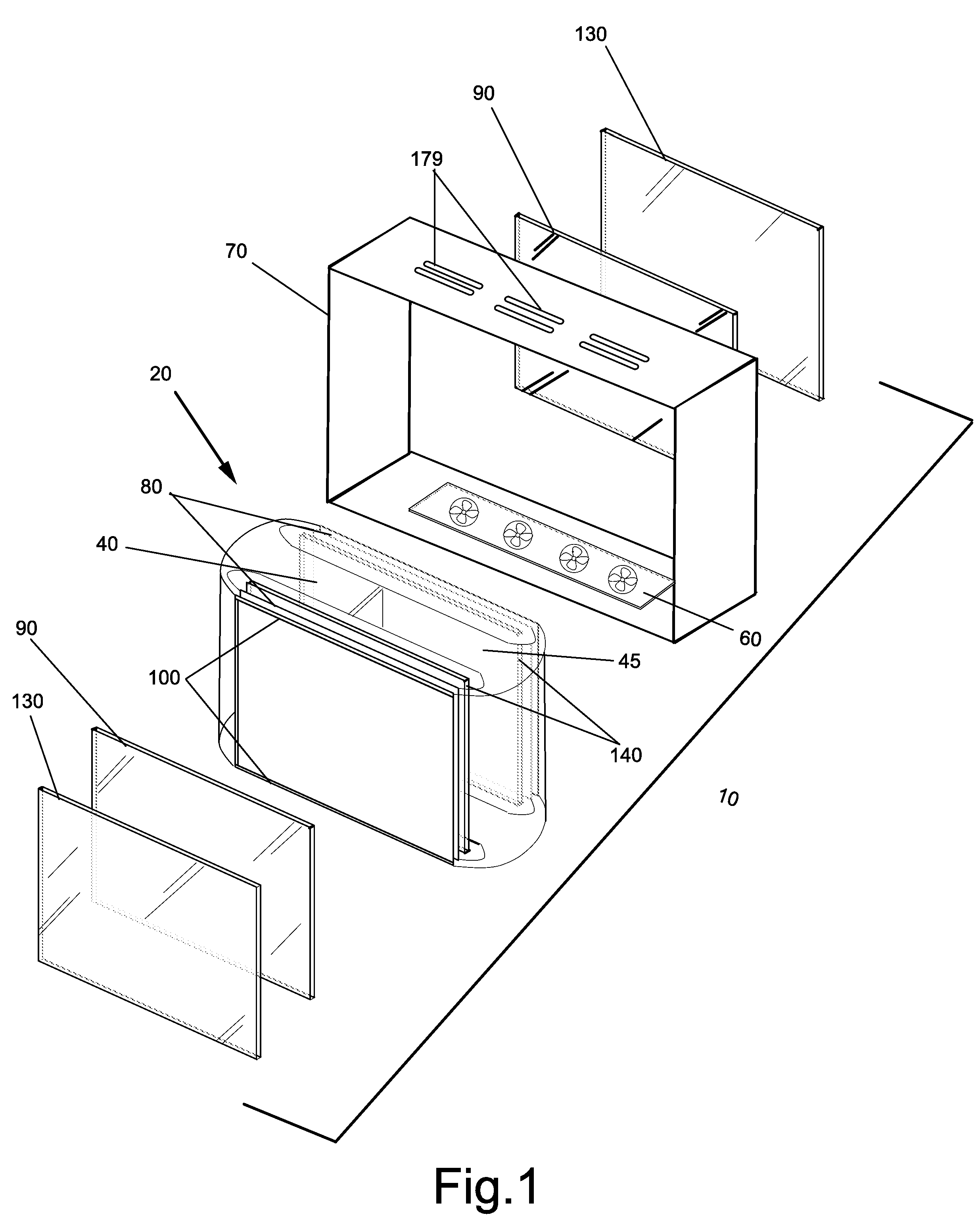
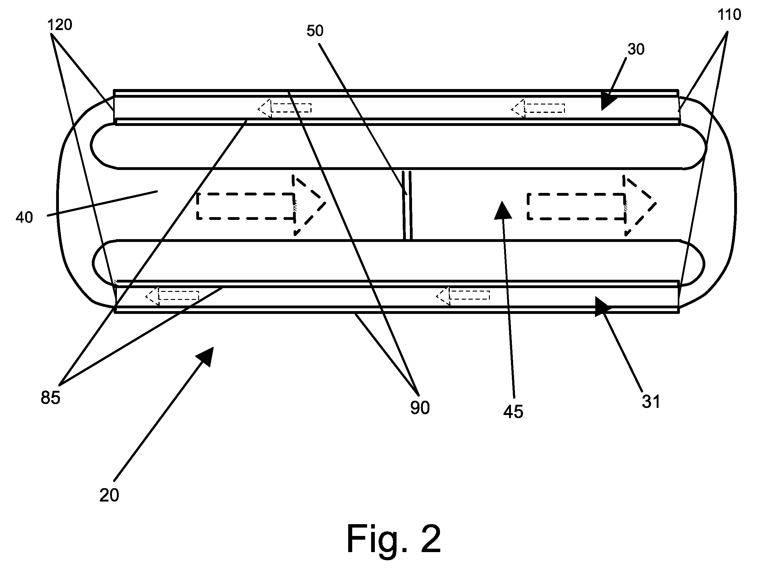
[0023]Referring to FIG. 1, the displays shown are equipped with an innovative gas cooling system. Accordingly, it may be placed in direct sunlight as well as warm ambient temperatures. As shown in FIG. 1 an exemplary embodiment 10 of the electronic display and gas cooling system includes an isolated gas cooling chamber 20 contained within an electronic display housing 70. In a preferred embodiment, the unit is substantially symmetrical with respect to the first and second gas chambers 30 and 31, thus features described for the first gas chamber 30 are similar to the features within the second gas chamber 31. Narrow transparent first gas chamber 30 and narrow transparent second gas chamber 31 may contain spacing members 100 and respective transparent front plates 90. A second transparent front plate 130 may be laminated to the exterior of transparent front plate 90 to help prevent breakage of front plate 90 or provide various optical properties (anti-reflection, polarization, phase r...


PUM


Abstract

A system and method for cooling back to back electronic displays. Transparent first and second gas chambers are co-existive with the front display surfaces of the first and second electronic displays. A closed loop of isolated gas enters the first and second gas chambers and contacts the front surfaces of the electronic displays, where it may extract heat from the front display surfaces. The isolated gas is then directed into a cooling chamber where it is cooled and re-introduced into the first and second gas chambers. Fans may be used to propel the isolated gas through the cooling chamber and the first and second gas chambers. The circulating gas removes heat directly from the electronic display surfaces. The isolated gas is transparent or at least semi-transparent to ensure that the image quality of the electronic displays is minimally impacted.

Description

CROSS-REFERENCE TO RELATED APPLICATIONS[0001]This application is a non-provisional application of U.S. Application No. 61 / 095,615 filed Sep. 9, 2008 and is hereby incorporated by reference. This application is also a continuation in part of U.S. patent application Ser. No. 11 / 941,728 filed Nov. 16, 2007, which is hereby incorporated by reference in its entirety. This application is also a continuation in part of U.S. patent application Ser. No. 12 / 191,834 filed Aug. 14, 2008, which claims priority to U.S. Application No. 61 / 033,058 filed Mar. 3, 2008 each of which is hereby incorporated by reference in its entirety. This application is also a continuation in part of U.S. patent application Ser. No. 12 / 234,307 filed Sep. 19, 2008, which claims priority to U.S. Application No. 61 / 033,064 filed Mar. 3, 2008 each of which is hereby incorporated by reference in its entirety. This application is also a continuation in part of U.S. patent application Ser. No. 12 / 234,360 filed Sep. 19, 2008...

Claims


Application Information

Patent Timeline
IPC IPC(8): H05K7/20F28F13/00F28D15/00
CPCG02F1/133385H05K7/20972G02F2201/36
Inventor DUNN, WILLIAM
Owner MFG RESOURCES INT INC
Why Eureka
Try Eureka