
Modular air conditioning system

Active Publication Date: 2010-09-16
TREAU INC
View PDF24 Cites 23 Cited by
  • Summary
  • Abstract
  • Description
  • Claims
  • Application Information

AI Technical Summary

Benefits of technology

[0010]In this regard, the present invention provides for a modular air conditioner that operates on the basic principal of a split system yet allows user serviceability and modular components such that the system is flexible. In accordance with the present invention a modular air conditioning system is provided that is optimized for efficiently cooling the occupants of a room. The system generally includes an outdoor unit, at least one indoor unit and a user serviceable hose that extends between the outdoor and indoor units. The outdoor unit contains a compressor, an air-cooled condenser, a coolant to fluid heat exchanger, a fan and various other components such as controls. While the indoor unit contains a fan, a fluid pump, a cold fluid storage tank and a fluid to air heat exchanger. Finally, the hose is a detachable hose that includes three lumens therein that act as a cold fluid supply, a fluid return and wiring for power and control signals.
[0011]In operation, the outdoor unit operates using a traditional heat pump / air conditioning cycle to reduce the temperature of the coolant or working fluid, which in turn extracts heat from a circulating fluid via the coolant to fluid heat exchanger. The cooled circulating fluid is then circulated, via the hose, between the outdoor and indoor units wherein the cooled fluid reduces the overall temperature of the cold fluid storage tank. When cooling is needed in the indoor space, cold fluid from the cold fluid storage tank is circulated through the fluid to air heat exchanger where the fan circulates room air across the heat exchanger producing a cooling effect. This arrangement allows the room cooling function and the fluid cooling function to be decoupled from one another in a temporal sense in that the control system only operates the outdoor unit when the temperature of the circulating fluid rises above a certain set point.
[0012]To further enhance the modularity of the system, the indoor and / or outdoor units are arranged such that they include multiple hose connection points so that multiple indoor units can be connected to a single outdoor unit. Such connections may be made directly from each of the indoor units to the outdoor units or in a daisy chain arrangement. Additionally, the indoor unit may include such functionality as heat sensors and servo directed louvers to direct cooling airflow to hotspots in a room (read here room occupants). Further, the indoor unit may be configured to collect condensate and deposit it back into the cold fluid loop. The outdoor unit can then be configured to eject some fluid from the loop should the fluid capacity of the loop be exceeded by the addition of condensate.
[0013]Accordingly, it is an object of the present invention to provide a modular air conditioner that operates on the basic principal of a split system yet allows user serviceability and modular components such that the system is flexible. It is a further object of the present invention to provide a modular air conditioning system that includes at least one indoor cooling unit that has a detachable cold storage therein such that the temperature of the cold store is maintained by a circulating coolant fluid through hose connections with an outdoor heat dissipation unit. It is still a further object of the present invention to provide a modular air conditioning system that includes at least one indoor cooling unit that has a detachable cold storage unit therein such that the cooling operation conducted by the indoor and outdoor units are temporally separated thereby allowing operation of the system at its highest efficiency.

Problems solved by technology

One of the difficulties encountered with prior art window air conditioners and unitary air conditioners is noise.
As a result, such units are typically noisy to operate.
Further, since the heat absorbing and heat discharging units are both positioned in the same housing, accommodations need to be made with respect to positioning of the units so that they do not operate as a closed loop within the room to be cooled.
This is done in the case of a window air conditioner by placing it in a window with the cooling portion on the interior and the heat discharge portion at the exterior, creating the additional problem of blocking a window.
Such installations require professional technicians to complete and charge the refrigerant piping, thereby greatly increasing the cost of the installation.
Such systems provide multiple zone control but require the permanent installation of a large and complex arrangement of pipes and automatic control valves.
In any of the above noted installations, there is very little an end user can do to service or reconfigure the air conditioning system.
While a user may install and remove a window mount or unitary air conditioner, the problem of noise within the space exists.
Still another difficulty with these prior types of installations is that they lack significant control over the directionality of the cooling.
While such devices have vanes or fins to direct the cooled air to some degree, the cooling is still limited to a region that surrounds the device.
Since the installation of the device is generally fixed, either because the unit sits in a window or the interior portion of a split system is permanently affixed to a wall, redirection of the cooling effect is nearly impossible.

Method used


Image

  • Modular air conditioning system
  • Modular air conditioning system
  • Modular air conditioning system

Examples


Embodiment Construction

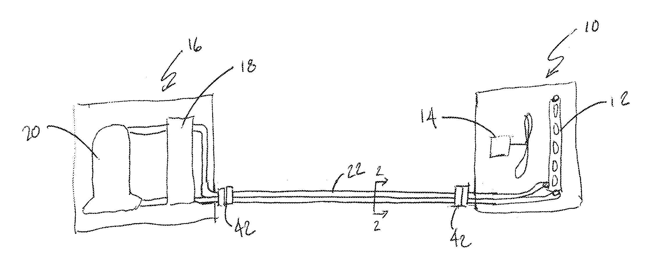
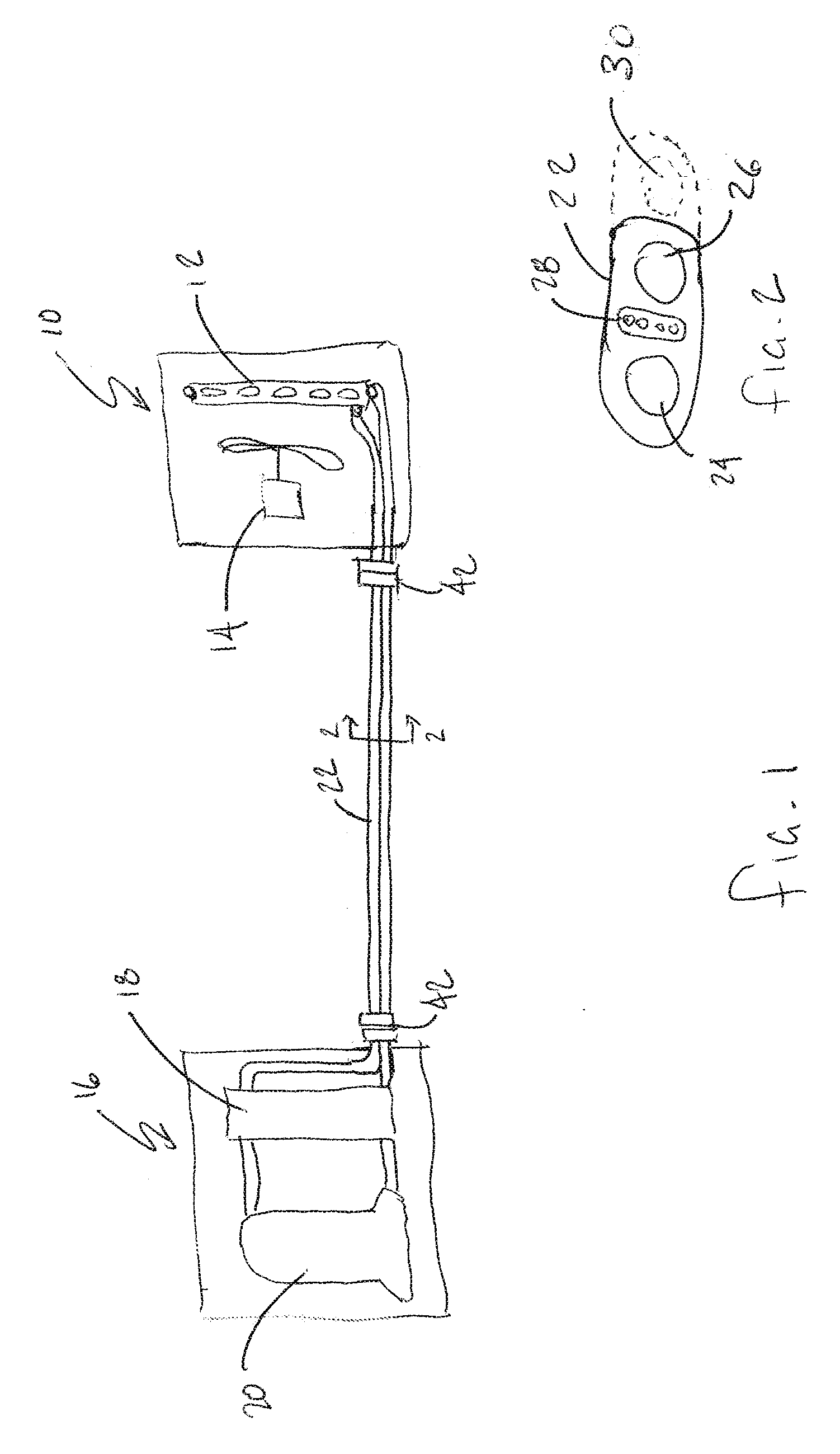
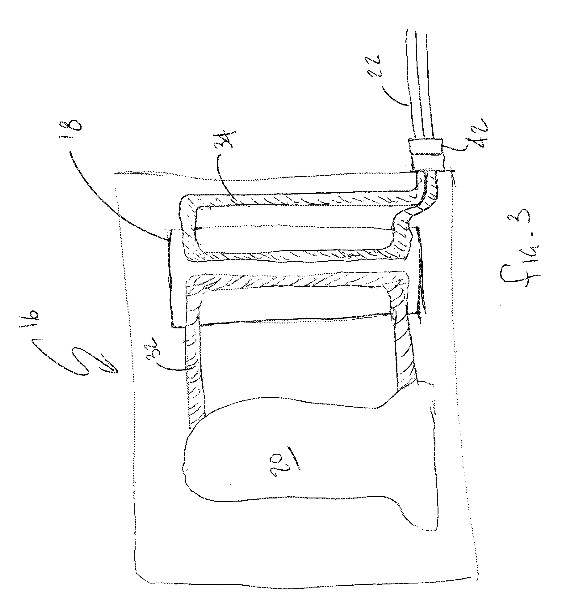
[0021]Now referring to the drawings, the modular climate control system is shown and generally illustrated in the figures. As can be seen at FIG. 1, the modular climate control system in its most general form includes at least one user positionable interior unit 10 wherein the interior unit 10 includes a fluid to air heat exchanger 12 and a fan 14 to circulate air across the fluid to air heat exchanger 12, an exterior unit 16 including a fluid to fluid heat exchanger 18 and a system 20 for supplying a working fluid having a controlled temperature to a first side of the fluid to fluid heat exchanger 18 and a circulation hose 22 connected between a fluid side of the fluid to air heat exchanger 12 and a second side of the fluid to fluid heat exchanger 18, wherein the circulation hose 22 allows a circulating fluid to transport heat between the at least one interior unit 10 and the exterior unit 16. As will be discussed in bore detail below, the circulating fluid is a non-toxic, user ser...


PUM


Abstract

A modular air conditioner is provided that operates on the basic principal of a split system yet allows user serviceability and modular components such that the system is flexible. The system generally includes an outdoor unit, at least one indoor unit and a user serviceable hose that extends between the outdoor and indoor units. The outdoor unit contains a compressor, an air-cooled condenser, a coolant to fluid heat exchanger, a fan and various other components such as controls. While the indoor unit contains a fan, a fluid pump, a cold fluid storage tank and a fluid to air heat exchanger. Finally, the hose is a detachable hose that includes three lumens therein that act as a cold fluid supply, a fluid return and wiring for power and control signals.

Description

CROSS-REFERENCE TO RELATED APPLICATIONS[0001]This application is related to and claims priority from earlier filed U.S. Provisional Patent Application No. 61 / 159,960, filed Mar. 13, 2009.BACKGROUND OF THE INVENTION[0002]The present invention relates generally to modular air conditioning systems. More specifically, the present invention relates to an air conditioning system that is formed to include an outdoor unit and at least one indoor unit, wherein the units are interconnected using a hose that is user serviceable and modular in a manner that allows reconfiguration and user serviceability as was previously unknown in the art.[0003]In the prior art there is a wide variety of devices available for cooling desired locations such as a room in a home. In the most general terms, these cooling devices draw heat from the room into a coolant working fluid. Once the fluid has absorbed the heat, it is then routed to a location that is remote from the room so that the heat absorbed into the ...

Claims


Application Information

Patent Timeline
IPC IPC(8): F25D21/14F25B13/00
CPCF24F1/0003F24F2221/36F24F1/34F24F1/32
Inventor BRADFORD, KIPPDECARVALHO, KASBRENDLER, THOMAS
Owner TREAU INC
Features
  • Generate Ideas
  • Intellectual Property
  • Life Sciences
  • Materials
  • Tech Scout
  • Unparalleled Data Quality
  • Higher Quality Content
  • 60% Fewer Hallucinations
Learn More