
Thin-film solar cell

Inactive Publication Date: 2010-09-16
SHEN KUO HUNG
View PDF7 Cites 59 Cited by
  • Summary
  • Abstract
  • Description
  • Claims
  • Application Information

AI Technical Summary

Benefits of technology

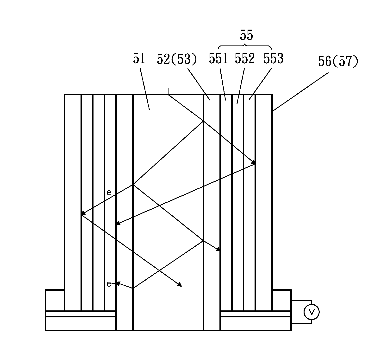
[0009]In accordance with the present invention, there is provided a thin-film solar cell, comprising an optical conduction cylinder made of a transparent material with a high light permeability, a transparent electrically conducting layer evenly plated on an axially extending peripheral surface of the optical conduction cylinder and having a peripheral wall provided with at least one inner electrode, at least one middle reaction layer plated on a peripheral surface of the electrically conducting layer and having an optical absorbing capacity to excite shifting of electrons and electric holes to produce an electric current, and a reflective layer plated on a peripheral surface of the middle reaction layer to prevent from permeation of a light and having a peripheral wall provided with at least one axially extending outer electrode which corresponds to the inner electrode of the electrically conducting layer.
[0010]According to the primary objective of the present invention, the reflective layer can reflect the sun light to prevent the sun light from permeating the reflective layer so that the sun light is enveloped in the optical conduction cylinder completely and is reflected successively in the reflective layer until the solar energy is exhausted such that the thin-film solar cell can absorb the solar energy to the maximum extent so as to enhance the light enveloping effect largely and to enhance the generating efficiency of the thin-film solar cell.
[0011]According to another objective of the present invention, the thin-film solar cell has a three-dimensional cylindrical profile by provision of the optical conduction cylinder, so that the illuminated area of the thin-film solar cell is increased to enhance the generating efficiency of the thin-film solar cell.
[0012]According to a further objective of the present invention, the area of the thin-film solar cell can be reduced under the same generating efficiency to reduce the volume and storage space of the thin-film solar cell.

Problems solved by technology

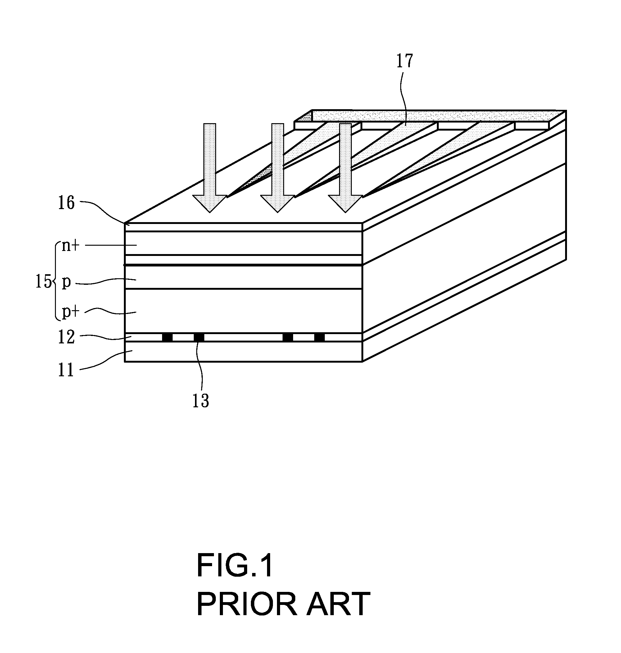
However, the conventional thin-film solar cell has a planar shape with a smaller illuminated area, thereby decreasing the generating efficiency of the conventional thin-film solar cell.
In addition, the conventional thin-film solar cell cannot envelop the sun light completely, and the sun light is reflected by the reflective layer 12 to form an energy loss during the reflected process of the sun light, thereby decreasing the generating efficiency of the conventional thin-film solar cell.
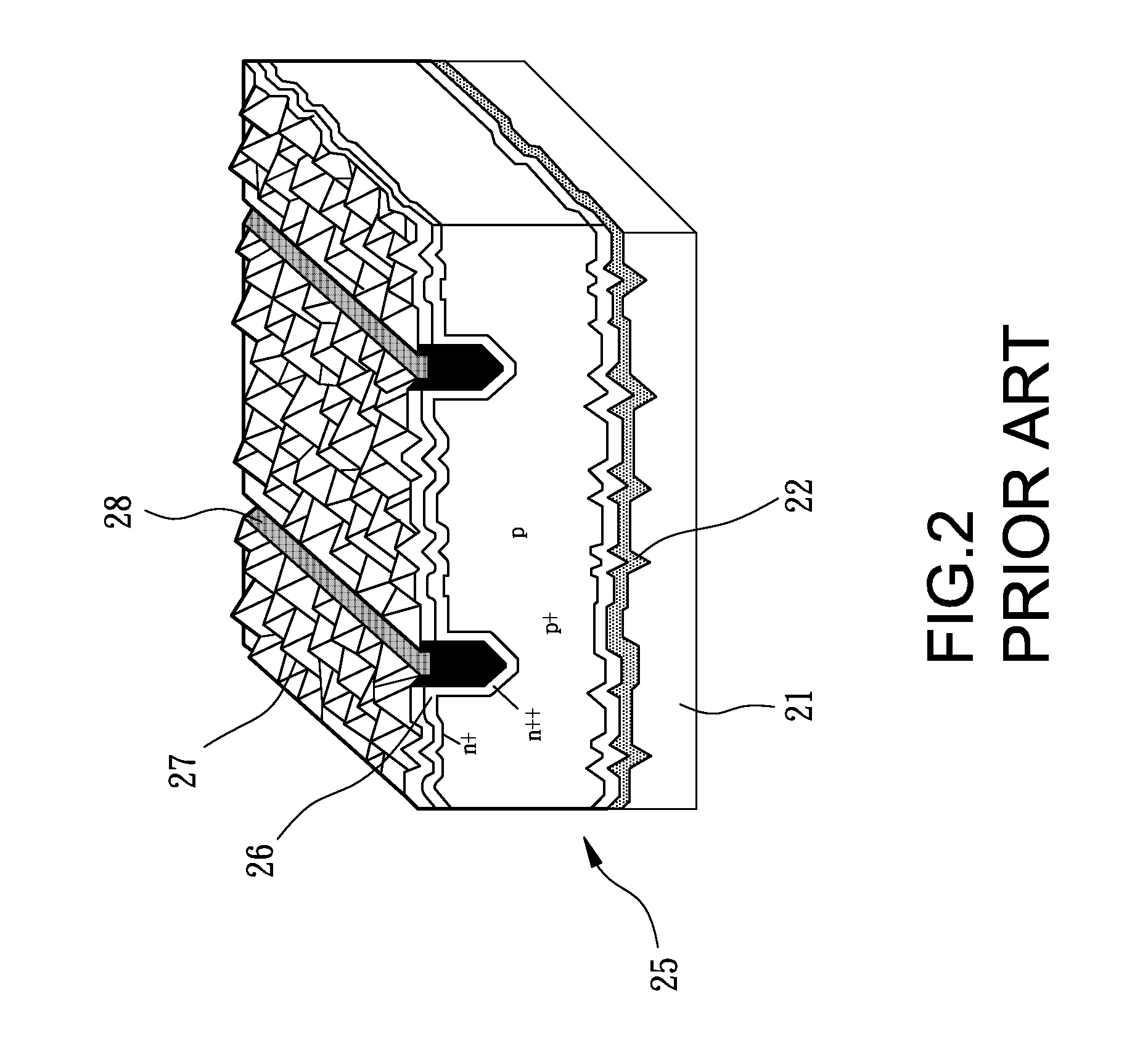
However, the conventional single-crystal silicon solar cell cannot envelop the sun light completely, and the sun light is reflected by the pyramidal surfaces 27 of the electrically conducting layer 26 to form an energy loss during the reflected process of the sun light, thereby decreasing the generating efficiency of the conventional thin-film solar cell.

Method used


Image

  • Thin-film solar cell
  • Thin-film solar cell
  • Thin-film solar cell

Examples


Embodiment Construction

[0026]Referring to the drawings and initially to FIGS. 1-5, a thin-film solar cell in accordance with the preferred embodiment of the present invention comprises an optical conduction cylinder 51 made of a transparent material with a high light permeability, a transparent electrically conducting layer 52 evenly plated on an axially extending peripheral surface of the optical conduction cylinder 51 and having a peripheral wall provided with at least one inner electrode 53, at least one middle reaction layer 55 plated on a peripheral surface of the electrically conducting layer 52 and having an optical absorbing capacity to excite shifting of electrons and electric holes to produce an electric current, and a reflective layer 56 plated on a peripheral surface of the middle reaction layer 55 to prevent from permeation of a light and having a peripheral wall provided with at least one axially extending outer electrode 57 which corresponds to the inner electrode 53 of the electrically con...


PUM


Abstract

A thin-film solar cell includes an optical conduction cylinder, a transparent electrically conducting layer evenly plated on an axially extending peripheral surface of the optical conduction cylinder, at least one middle reaction layer plated on a peripheral surface of the electrically conducting layer, and a reflective layer plated on a peripheral surface of the middle reaction layer. Thus, the reflective layer can reflect the sun light to prevent from permeation of the sun light so that the sun light is enveloped in the optical conduction cylinder completely and is reflected successively in the reflective layer until the solar energy is exhausted such that the thin-film solar cell can absorb the solar energy to the maximum extent to enhance the light enveloping effect largely and to enhance the generating efficiency of the thin-film solar cell.

Description

BACKGROUND OF THE INVENTION[0001]1. Field of the Invention[0002]The present invention relates to a solar cell and, more particularly, to a thin-film solar cell.[0003]2. Description of the Related Art[0004]A conventional thin-film solar cell in accordance with the prior art shown in FIG. 1 comprises a substrate 11, a reflective layer 12 plated on a surface of the substrate 11 and having a surface provided with at least one inner electrode 13, at least one middle reaction layer 15 plated on a surface of the reflective layer 12, and a transparent electrically conducting layer 16 plated on a surface of the middle reaction layer 15 and having a surface provided with at least one outer electrode 17 which is connected serially with the inner electrode 13 of the reflective layer 12. The electrically conducting layer 16 has a photo conductive effect. The middle reaction layer 15 includes at least one P+ semi-conductor layer plated on the reflective layer 12 to produce electric holes, at leas...

Claims


Application Information

Patent Timeline
IPC IPC(8): H01L31/00
CPCH01L31/0232Y02E10/52H01L31/0522H01L31/035281H01L31/022425H01L31/03921H01L31/068Y02E10/547H01L31/056H01L31/0547
Inventor SHEN, KUO-HUNG
Owner SHEN KUO HUNG
Learn More