Photonic filtering of electrical signals

a photonic filtering and electrical signal technology, applied in the direction of rf signal generation/processing, optical transmission for rf signal generation/processing, instruments, etc., can solve the problems of long time, low frequency accuracy, and the loss of circuit board based planar structures at higher frequencies, so as to achieve reliable, wide-ranging tunable filtering of electrical signals. , the effect of simple structur

Inactive Publication Date: 2010-09-16
HER MAJESTY THE QUEEN & RIGHT OF CANADA REPRESENTED BY THE MIN OF IND THROUGH THE COMM RES CENT
View PDF23 Cites 22 Cited by
  • Summary
  • Abstract
  • Description
  • Claims
  • Application Information

AI Technical Summary

Benefits of technology

[0015]Advantageously, the present invention does not require multiple optical paths for downshifting the carrier frequency back into

Problems solved by technology

It is rather difficult to predict the information carrying capacity of individual beams during such a long period of time.
However, the circuit board based planar structures tend to be lossy at higher frequencies due to radiative loss.
Coaxial structures are superior in this regard because the outer conductor shields the structure, but these tend to be bulky and heavy.
Millimeter-wave filters can be formed using dielectric resonators and cavity structures, but they are difficult to fabricate, and the resulting filter characteristics can be very sensitive to fabrication errors, particularly when the filters contain multiple coupled resonators.
Both the microwave and the millimeter-wave filters are difficult to tune and have a limited tuning range.
Furthermore, it is dif

Method used


Image

  • Photonic filtering of electrical signals
  • Photonic filtering of electrical signals
  • Photonic filtering of electrical signals

Examples


Embodiment Construction

[0042]While the present teachings are described in conjunction with various embodiments and examples, it is not intended that the present teachings be limited to such embodiments. On the contrary, the present teachings encompass various alternatives, modifications and equivalents, as will be appreciated by those of skill in the art.

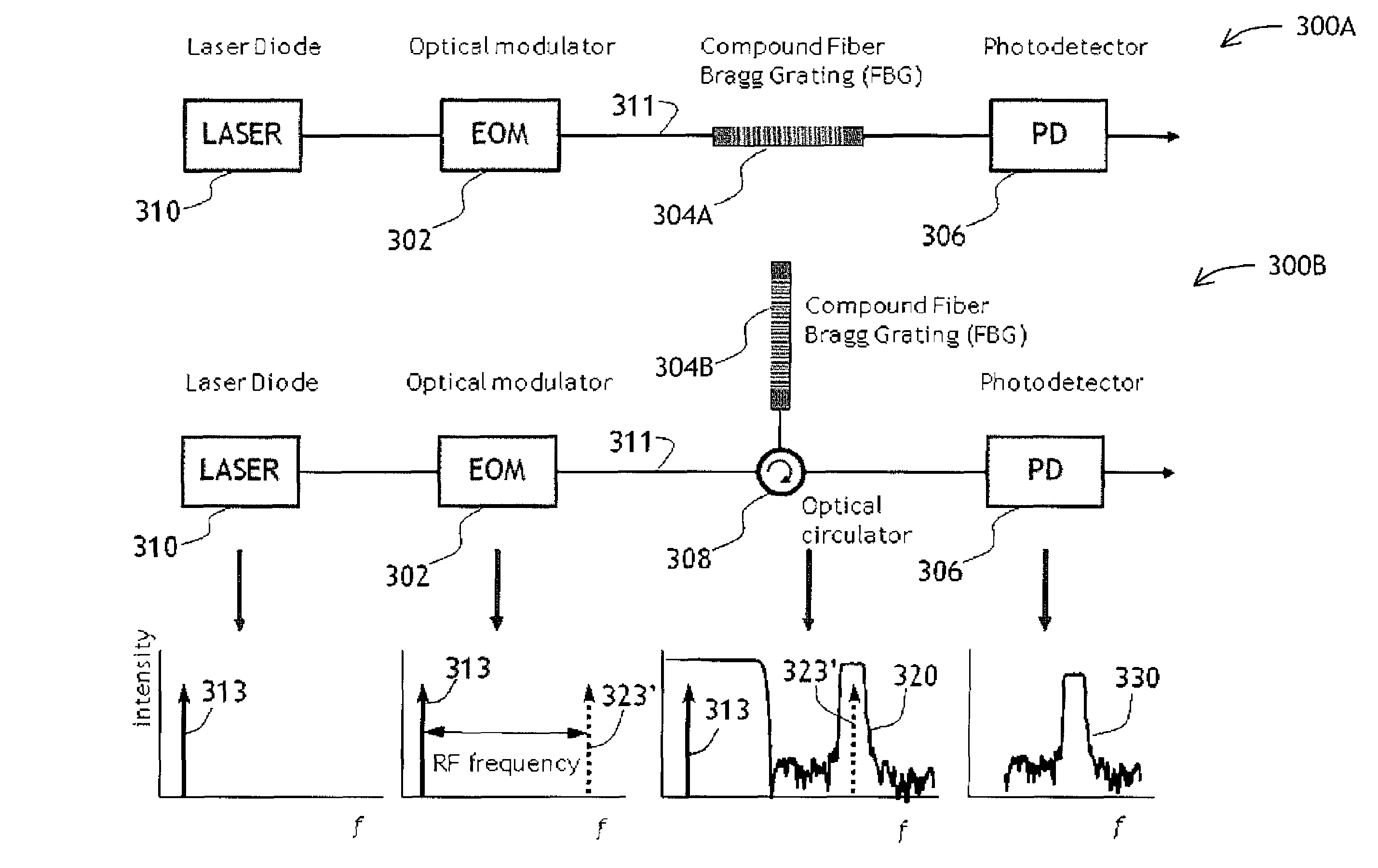
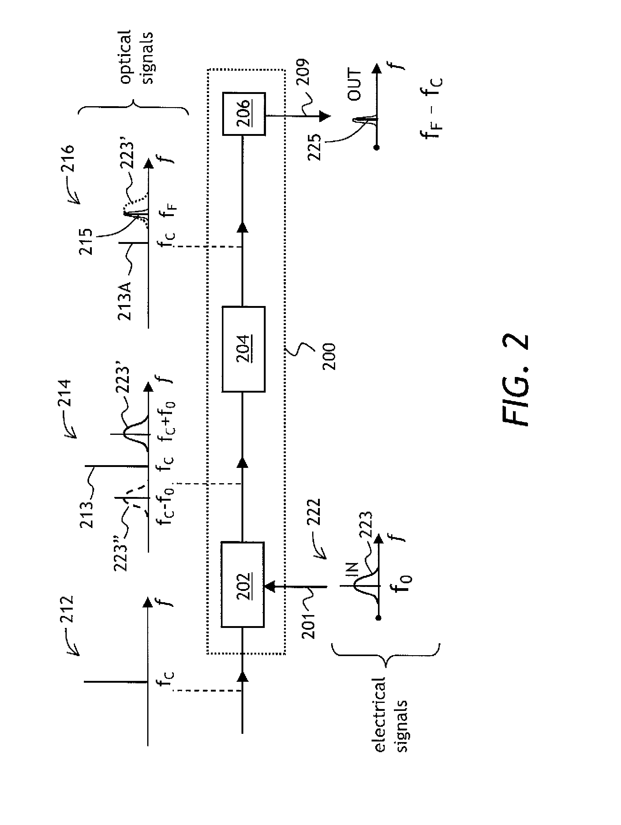
[0043]Referring to FIG. 2, a diagrammatic view of a filter 200 of the present invention is shown. The filter 200 has an optical modulator 202 for receiving light at a carrier frequency fC and for modulating the received light with an input electrical signal 201 represented by a spectral band 223 centered at a frequency f0; an optical filter 204 coupled to the optical modulator 202, for receiving the modulated light and for filtering light at a filtering frequency fF; and a photodetector 206 coupled to the optical filter 204, for detecting light at a beat frequency between the filtering and carrier frequencies fF and fC.

[0044]In operation, an optical signa...


PUM


Abstract

A filter and a method of filtering a high frequency electrical signal using photonic components is disclosed. The filter has a serially fiber-coupled laser source, a modulator, a filter, and a photodetector. The electrical signal is applied to the modulator. The modulated light propagates through the filter which is constructed to pass not only a modulated sideband, but also at least a fraction of light at the carrier frequency of the laser. The photodetector detects a signal at the beat frequency between the carrier and sideband signals, after both signals have propagated through the filter. As a result, a separate optical branch for light at the carrier frequency is not required, which considerably simplifies the filter construction and makes it more stable and reliable.

Description

CROSS-REFERENCE TO RELATED APPLICATIONS[0001]The present invention claims priority from U.S. provisional patent application No. 61 / 158,792, filed Mar. 10, 2009, which is incorporated herein by reference.TECHNICAL FIELD[0002]The present invention relates to signal filtering, and in particular to photonic filtering of electrical signals.BACKGROUND OF THE INVENTION[0003]Communication satellites operating in the Ka-band frequency range often use a large number of microwave communication beams. The satellites typically have a lifetime of over 15 years. It is rather difficult to predict the information carrying capacity of individual beams during such a long period of time. Accordingly, dynamic allocation of the bandwidth among the microwave communication beams is highly desirable.[0004]The dynamic bandwidth allocation can be provided by tunable microwave filters having a tunable central frequency and a variable width of the passband. Such tunable microwave filters can be installed in bot...

Claims


Application Information

Patent Timeline
IPC IPC(8): G02B27/00
CPCG02F1/01G02F2201/16H04B2210/006G02F2203/055G02F2201/307G02B2006/12109
Inventor RIDEOUT, HOWARDSEREGELYI, JOELU, PINGPAQUET, STEPHANEYAO, JIANPINGMIHAILOV, STEPHEN J.OLDHAM, JOHNCARON, MARIO
Owner HER MAJESTY THE QUEEN & RIGHT OF CANADA REPRESENTED BY THE MIN OF IND THROUGH THE COMM RES CENT
Why Eureka
Try Eureka