Vehicle suspension system

a suspension system and vehicle body technology, applied in the direction of shock absorbers, machine supports, transportation and packaging, etc., to achieve the effect of reducing influence, reducing frame influence, and relatively high stiffness of the vehicle body

Active Publication Date: 2010-09-16
TOYOTA JIDOSHA KK
View PDF15 Cites 62 Cited by
  • Summary
  • Abstract
  • Description
  • Claims
  • Application Information

AI Technical Summary

Benefits of technology

[0006]The constant-force generating state is a state in which the actuator keeps generating a force that could change a distance a wheel and a vehicle body. By controlling the constant-force generating state, it is possible to effectively control discharge of the battery. Such a technical effect enables the suspension system according to the present invention to have a high serviceability in the practical use.(B) Modes of the Invention
[0061]Since the battery is discharged by the establishment of the constant-force generating state, as described above, the establishment of the constant-force generating state during the low-charged state of the battery causes a situation in which the electric energy remaining in the battery is extraordinarily reduced, or could cause even a situation in which the battery is placed in the excessively-discharged state. In the present mode, it is possible to effectively prevent or restrain harm caused by the establishment of the constant-force generating state when the charge level of the battery is low. The term “limiting establishment of the constant-force generating state” is interpreted to mean not only inhibition of the establishment of the constant-force generating state but also reduction of degree of the constant-force generating state such as reduction of the constant actuator force. Further, specifically, it is possible to employ an arrangement in which the establishment of the constant-force generating state is inhibited when the charge level becomes equal to or lower than a threshold (for example, when a parameter indicative of the charge state of the battery becomes equal to or lower than the threshold).

Problems solved by technology

However, depending on a charge state of the battery, there could be a situation where the electric power should not be supplied from the battery or a situation where the electric power should not be returned to the battery.

Method used


Image

  • Vehicle suspension system
  • Vehicle suspension system
  • Vehicle suspension system

Examples


first embodiment

1. Construction and Function of Suspension System

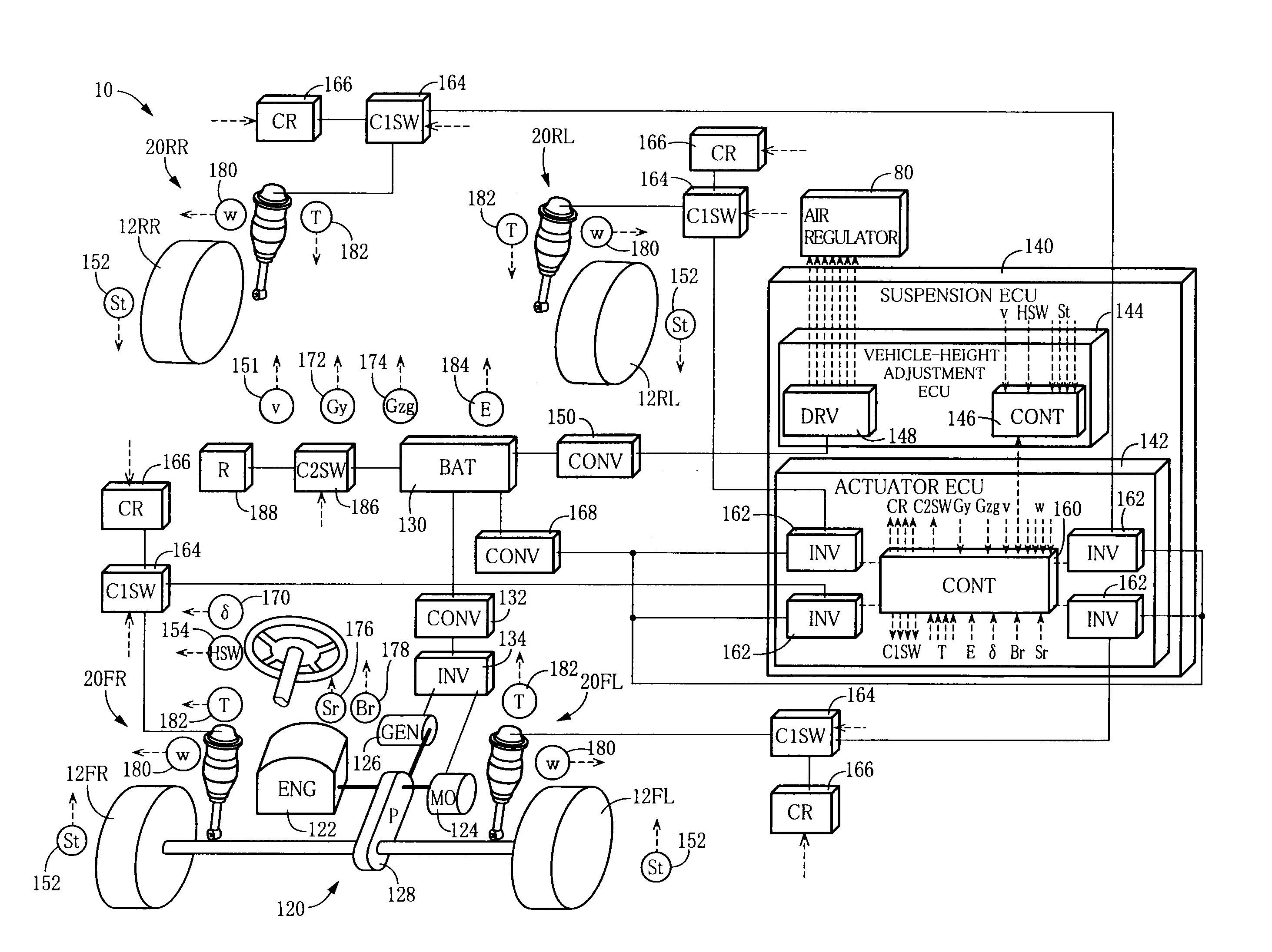
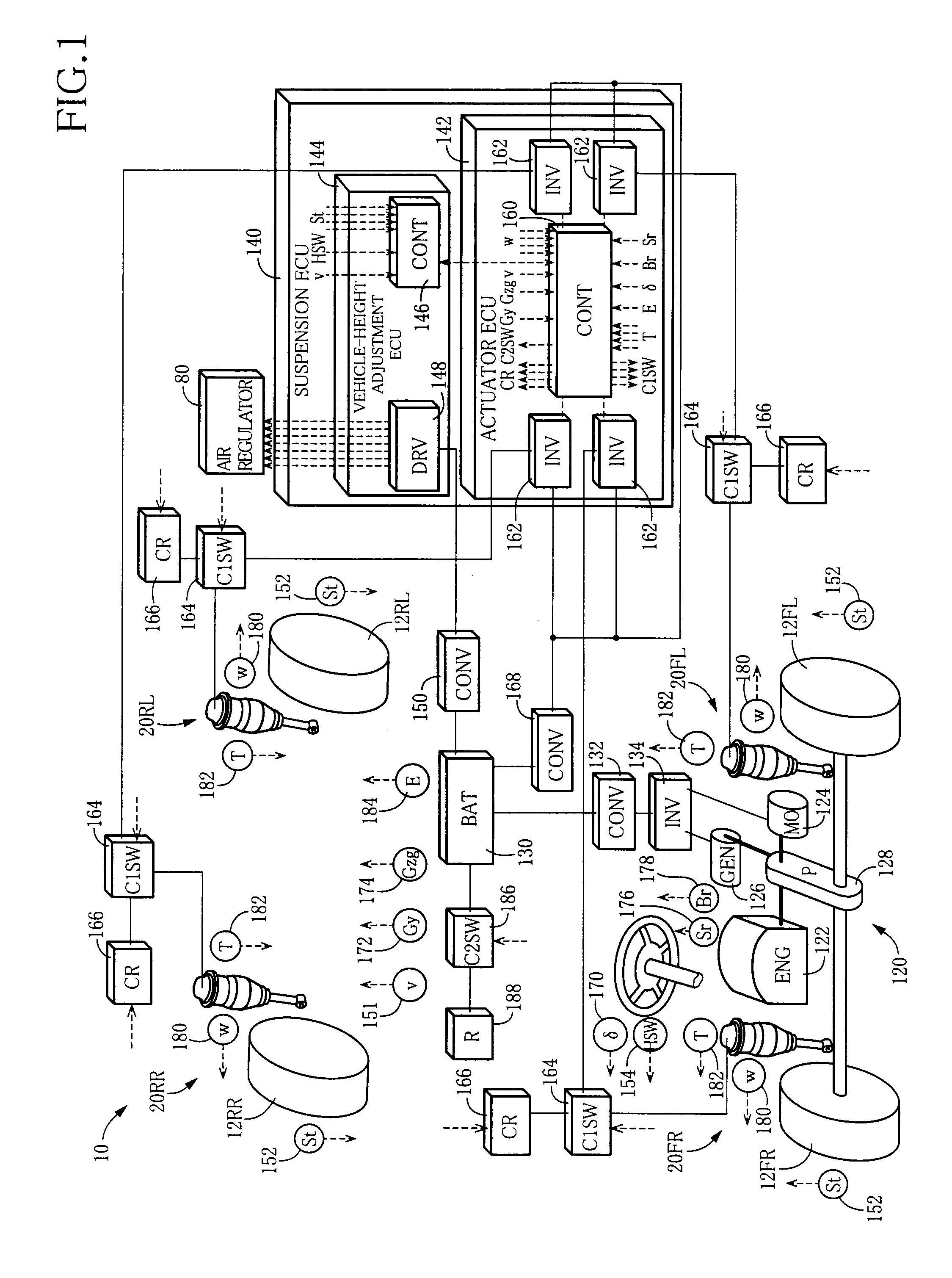
[0097]FIG. 1 schematically shows a vehicle suspension system 10 constructed according to a first embodiment of the invention. The suspension system 10 is equipped with four independent suspension devices provided for front right, front left, rear right and rear left wheels 12 of a vehicle. Each of the suspension devices has a spring absorber assembly 20 constituted by a suspension spring and a shock absorber that are integral with each other. In the following description, each of the wheel 12 and spring absorber assembly 20 is referred together with, as a suffix, one of reference signs FR, FL, RR, RL indicative of the respective front right, front left, rear right and rear left wheels, where it should be clarified which one of the four wheels the referred wheel 12 or assembly 20 corresponds to.

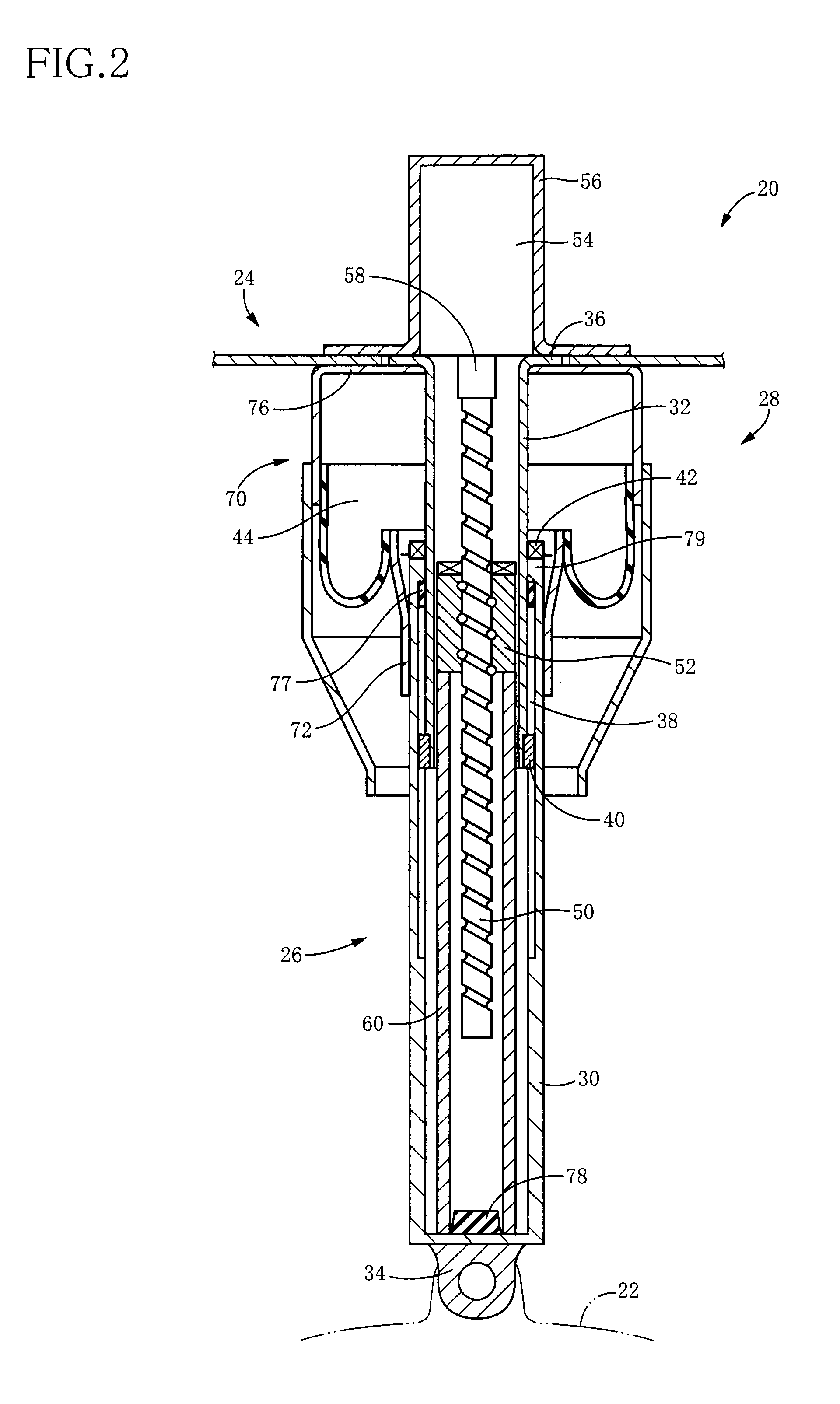
[0098]As shown in FIG. 2, the spring absorber assembly 20 is equipped with an electromagnetic shock absorber in the form of an actuator 26 and ...

second embodiment

1. Construction of Suspension System

[0141]In the vehicle suspension system according to present embodiment, although the vehicle-height adjusting control by the air spring is not executed, the other controls are executed substantially in the same manner as the actuator control in the above-described embodiment. FIG. 23 schematically shows a vehicle suspension system 220 of the present embodiment. Since the present suspension system 220 is equipped with many constructional elements that are common to the vehicle suspension system 10, the same reference signs as used in the above-described embodiment will be used to identify the common constructional elements, and description of these elements is omitted or simplified.

[0142]The present suspension system 220 is equipped with a spring absorber assembly 222. As shown in FIG. 24, the spring absorber assembly 222 is equipped with the electromagnetic shock absorber in the form of the actuator 26 and the suspension spring in the form of a co...

third embodiment

1. Construction of Suspension System

[0153]FIG. 28 schematically shows a vehicle suspension system 250. Since the present suspension system 250 is substantially the same as the above-described suspension system 220 except for various sensors required for execution of the controls, the same reference signs as used in the above-described embodiment will be used to identify the common constructional elements, and description of these elements is omitted or simplified.

2. Vehicle-Height Adjusting Control

[0154]In the present system 250, all the four actuator 26 provided for the respective four wheels 12 are caused to generate the constant forces in the same direction, for actively changing the vehicle height. Described in detail, the four actuators 26 are caused to generate the constant forces acting in the rebound direction for increasing the vehicle height, and are caused to generate the constant forces acting in the bound direction for reducing the vehicle height. That is, in the presen...


PUM


Abstract

A vehicle suspension system including: (a) a suspension spring interconnecting a vehicle body and a wheel; (b) an actuator having an electric motor, such that the actuator is capable of generating, based on a force of the electric motor, an actuator force forcing the body and the wheel toward and away from each other, and causing the generated actuator force to act as a damping force against displacement of the body and the wheel; and (c) a control device for controlling the actuator force generated by the actuator, by controlling operation of the electric motor. The control device is capable of establishing a constant-force generating state in which the actuator force is constantly generated as a constant actuator force by the actuator with supply of an electric power thereto from a battery as an electric power source of the electric motor such that the generated constant actuator force acts in a rebound direction or a bound direction. The control device controls the constant-force generating state, based on a charge state of the battery.

Description

TECHNICAL FIELD[0001]The present invention relates in general to a suspension system that is to be installed in a vehicle, and more particularly to such a suspension system equipped with an electromagnetic actuator that functions as a shock absorber.BACKGROUND ART[0002]In vehicle industry field of recent years, there is a development of a system disclosed in patent document identified below, i.e., a so-called electromagnetic suspension system (hereinafter abbreviated to as “electromagnetic suspension” where appropriate) in which an electromagnetic actuator is arranged to function as a shock absorber (damper). This electromagnetic suspension is expected as high-performance suspension system, owing to its advantages such as easy establishment of suspension characteristic based on a so-called skyhook theory.[0003][Patent Document 1] JP2002-311452ADISCLOSURE OF THE INVENTION(A) Outline of the Invention[0004]In the electromagnetic suspension disclosed in the above-identified patent docum...

Claims


Application Information

Patent Timeline
Patent Type & Authority Applications(United States)
IPC IPC(8): F16F15/03
CPCB60G11/27B60G13/14B60G15/02B60G17/015B60G17/0157F16F2232/06B60G2202/42B60G2300/60B60G2400/102B60G2400/252B60G2202/12
Inventor INOUE, HIROFUMIDATE, HIROAKIOGAWA, KAZUO
Owner TOYOTA JIDOSHA KK
Why Eureka
Try Eureka