Eureka AIR delivers breakthrough ideas for toughest innovation challenges, trusted by R&D personnel around the world.

System and Method of Clock Tree Synthesis

a clock tree and clock signal technology, applied in the field of system and method of clock tree synthesis, can solve the problems of wasting power, affecting the user experience, and affecting the quality of clock signals, so as to reduce the delay uncertainty, reduce the delay, and save power.

Active Publication Date: 2010-09-16
QUALCOMM INC
View PDF10 Cites 21 Cited by
  • Summary
  • Abstract
  • Description
  • Claims
  • Application Information

AI Technical Summary

Benefits of technology

The patent describes a method and device for generating an advanced gating cell clock tree. The method involves determining a timing margin for a path between a clock gating cell and a digital data storage element, such as a latch or flip flop. When the timing margin exceeds a predetermined threshold, the clock gating cell is automatically moved closer to the clock source. The device includes a circuit with a clock tree designed using an automated circuit design tool. Buffers are inserted along a path to reduce clock phase delay and deviation of the clock signal, which helps to reduce delay uncertainty and ensure correct data latching. The method and device conserve power by moving the clock gating cell away from the logic gates.

Problems solved by technology

However, power consumption of such portable devices can quickly deplete a battery and diminish a user's experience.
The clock tree often consumes a significant portion of the power consumed by a semiconductor device and some of the power can be wasted in a branch of a clock tree when the output of the branch is not needed.
Unfortunately, the clock gating cell is often located close to the logic gates resulting in some areas that could be turned off not being turned off and thereby consuming added power.
Clock phase delay and deviations of the clock signal from a target value result in delay uncertainty that can cause incorrect data to be latched within a register.

Method used


Image

  • System and Method of Clock Tree Synthesis
  • System and Method of Clock Tree Synthesis
  • System and Method of Clock Tree Synthesis

Examples


Embodiment Construction

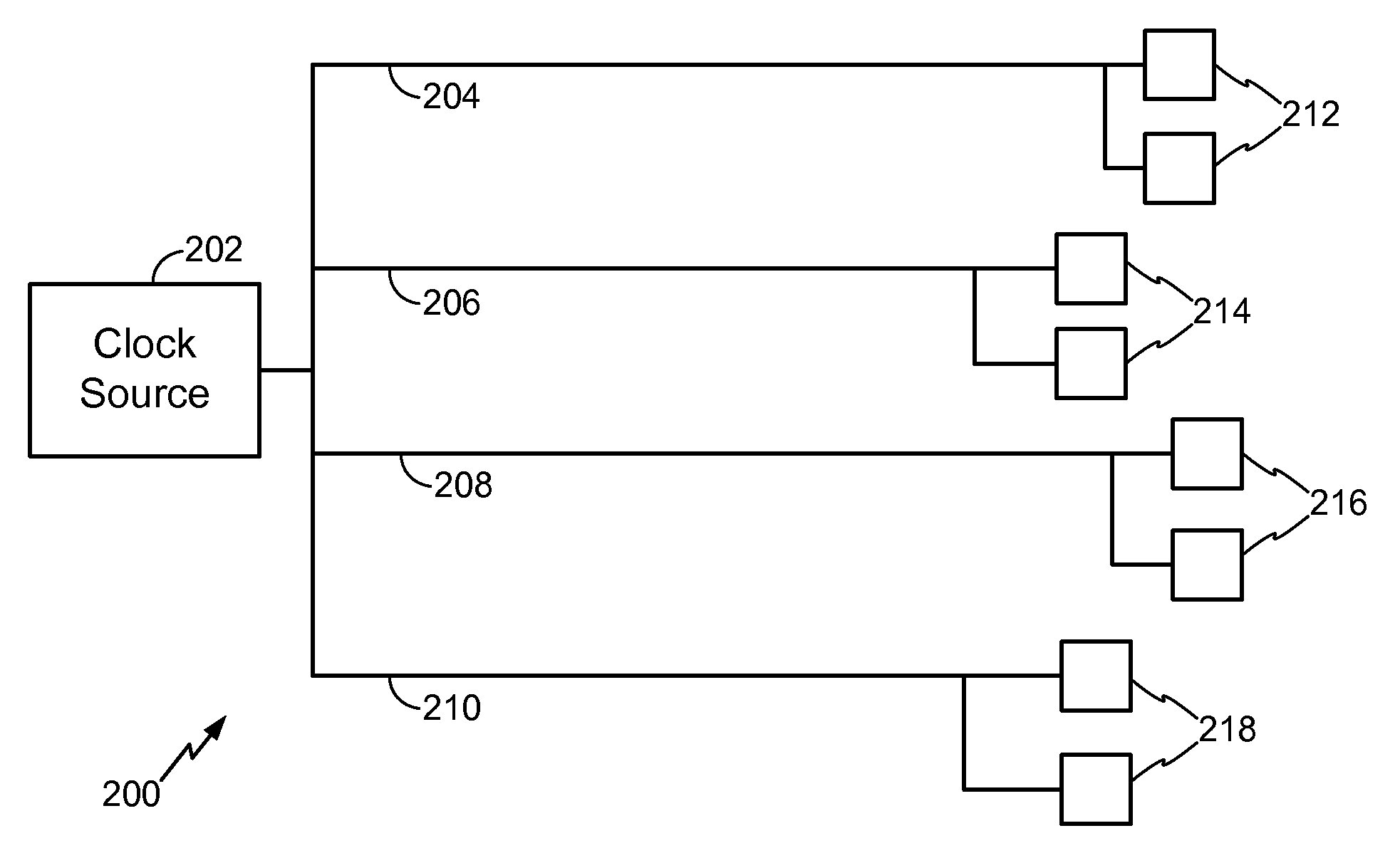
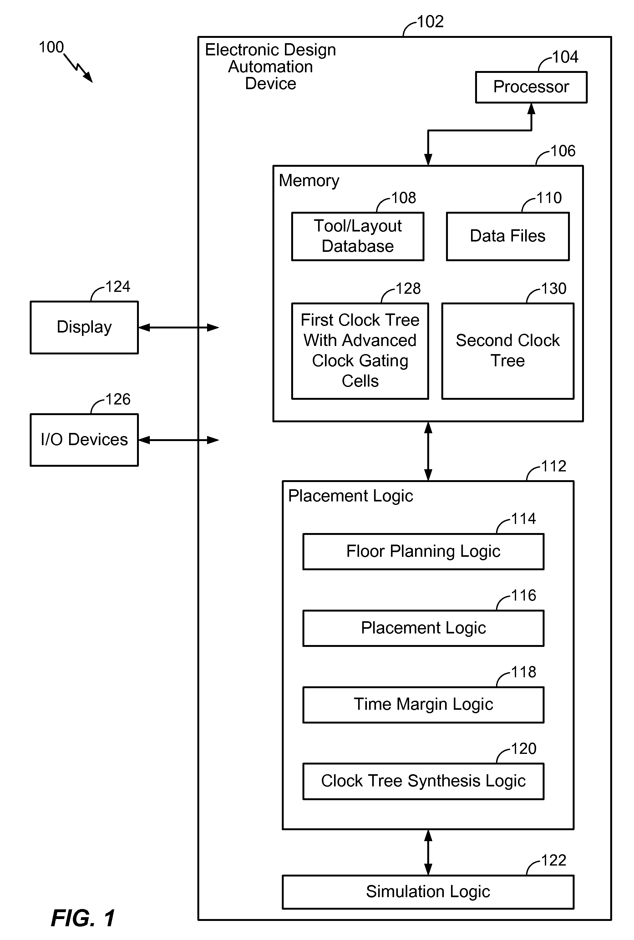
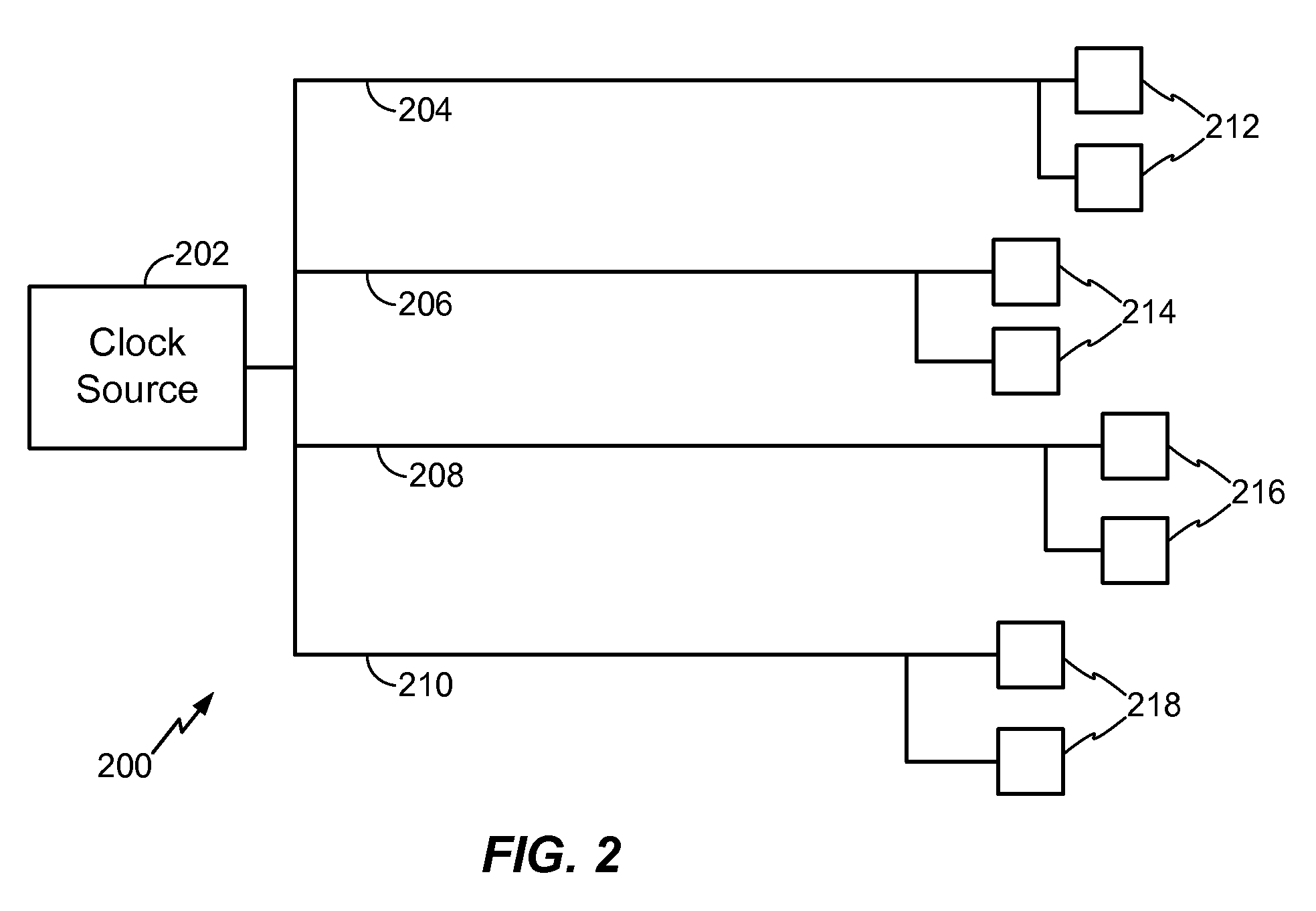
[0020]Referring to FIG. 1 an illustrative embodiment of a system to perform a clock tree synthesis and create an advanced gating cell clock tree is depicted and generally designated 100. The system 100 includes an electronic design automation device 102, a display device 124, and input / output (I / O) devices 126. The display device 124 may be a computer screen or other visual screen to visually display output from the electronic design automation device 102. The I / O devices 126 are input and output devices used to control the electronic design automation device 102. The electronic design automation device 102 is a tool to enable designing and producing electronic systems that contain a clock tree. The electronic design automation device 102 contains a processor 104 coupled to memory 106, placement logic 112, and simulation logic 122.

[0021]The memory 106 contains a tool / layout database 108 and data files 110. The tool / layout database 108 contains tools and layouts to design a circuit w...


PUM


Abstract

In a particular embodiment, a method of generating an advanced gating cell clock tree includes determining a timing margin for a path between a clock gating cell and a digital data storage element such as a latch or flip flop. The circuit contains a clock source and when the timing margin for the path meets a predetermined threshold, the clock gating cell is automatically moved closer to the clock source. In a particular embodiment, the timing margin is automatically determined. A clock tree synthesis is performed to insert one or more buffers into the path and create an advanced gating cell clock tree.

Description

I. FIELD[0001]The present disclosure is generally related to a system and method of clock tree synthesis.II. DESCRIPTION OF RELATED ART[0002]Advances in technology have resulted in smaller and more powerful personal computing devices. For example, there currently exist a variety of portable personal computing devices, including wireless computing devices, such as portable wireless telephones, personal digital assistants (PDAs), and paging devices that are small, lightweight, and easily carried by users. More specifically, portable wireless telephones, such as cellular telephones and IP telephones, can communicate voice and data packets over wireless networks. Further, many such wireless telephones include other types of devices that are incorporated therein. For example, a wireless telephone can also include a digital still camera, a digital video camera, a digital recorder, and an audio file player. Also, such wireless telephones can process executable instructions, including softw...

Claims


Application Information

Patent Timeline
Patent Type & Authority Applications(United States)
IPC IPC(8): G06F1/04G06F17/50
CPCG06F1/10G06F17/505H04L7/0008G06F2217/84G06F2217/62G06F30/396G06F30/327G06F2119/12G06F2117/04
Inventor SINGASANI, CHANDRASEKHAR
Owner QUALCOMM INC
Why Eureka
Eureka Blog
Learn More