
Control circuit for forming process on nonvolatile variable resistive element and control method for forming process

a technology of resistive element and control circuit, which is applied in the direction of digital storage, instruments, semiconductor devices, etc., can solve the problems far from realizing the ideal of universal memory, and achieve the effect of shortening the forming tim

Inactive Publication Date: 2010-09-16
SHARP KK
View PDF6 Cites 16 Cited by
  • Summary
  • Abstract
  • Description
  • Claims
  • Application Information

AI Technical Summary

Benefits of technology

[0025]The control method for a forming process according to the present invention is a control method for a forming process on a nonvolatile variable resistive element in a nonvolatile semiconductor memory device, the nonvolatile semiconductor memory device comprising a memory cell array where memory cells are aligned in a matrix, each memory cell being formed by connecting one terminal of a nonvolatile variable resistive element with two terminals having electrodes at both ends of a variable resistor to one terminal of a selection element with two terminals for controlling the current flowing through the selection element through application of a voltage across the two terminals, or one of the two terminals other than a control terminal of a selection element with three terminals for controlling the current flowing between the two terminals through application of a current or a voltage to the control terminal, first characterized in that the memory cells are connected to each other within the memory cell array through first selection lines extending in the direction of rows for connecting the memory cells in the same row, and second selection lines extending in the direction of columns for connecting the memory cells in the same column, a forming process makes the nonvolatile variable resistive element transit between two or more different resistance states when electrical stress is applied across the two terminals of the nonvolatile variable resistive element, so that one resistance state after the transition can be used for storing information, the control method for the forming process comprises: selecting one first selection line having a connection to the memory cells on which the forming process is to be carried out within the memory cell array; selecting the second selection lines individually having connection to the memory cells on which the forming process is to be carried out within the memory cell array; applying a forming voltage for the forming process simultaneously to the selected second selection lines; detecting fluctuation in the current flowing through a predetermined point along the second selection line or the potential at a predetermined point along the second selection line due to completion of the forming process; and preventing the forming voltage from being applied to the second selection line for which the fluctuation in the current or potential is detected, and the forming process is carried out simultaneously on the nonvolatile variable resistive elements of the memory cells having connection to the same first selection line.
[0026]The present invention allows a nonvolatile semiconductor memory device having a memory cell array where unit memory cells each having a nonvolatile variable resistive element with two terminals and a selection element are aligned in a matrix to be provided with a control means for detecting the completion of a forming process on memory cells having individual connection to a second selection line, and preventing a voltage pulse for a forming process from being applied through the second selection line having connection to the memory cell for which the completion of the forming process is detected, so that the fluctuation in the potential of the second selection line due to the completion of the forming process is reset, and the voltage required for the forming process can be supplied to the nonvolatile variable resistive elements of other memory cells where the forming process has not yet completed.
[0029]Accordingly, a forming process can be carried out simultaneously and collectively on a number of memory cells that are connected to the same first selection line, and thus, it is possible to shorten the forming time.

Problems solved by technology

However, these memory devices currently have both good and bad points, and we are far away from realizing an ideal “universal memory” having all the good points of SRAMs, DRAMs and flash memories.
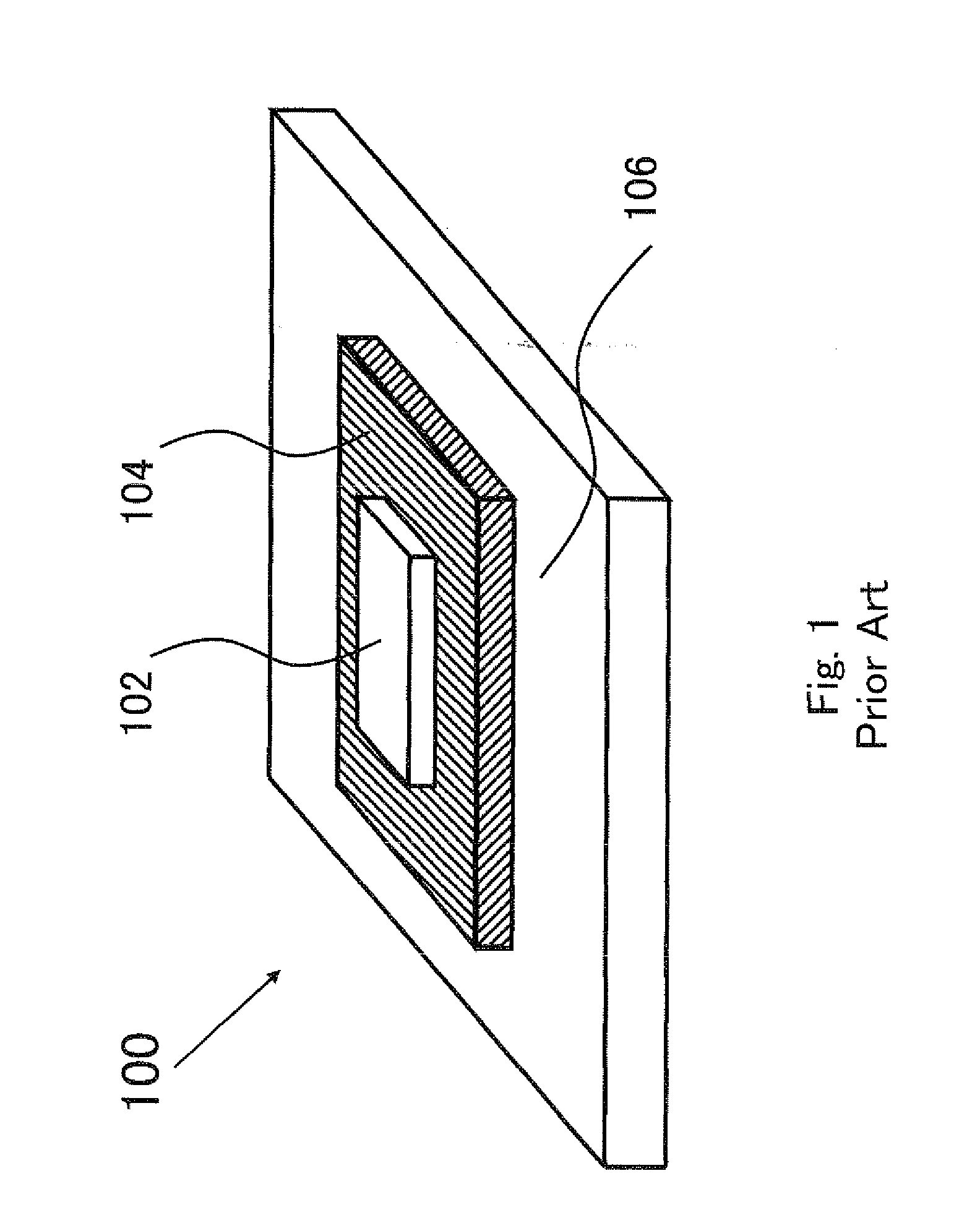
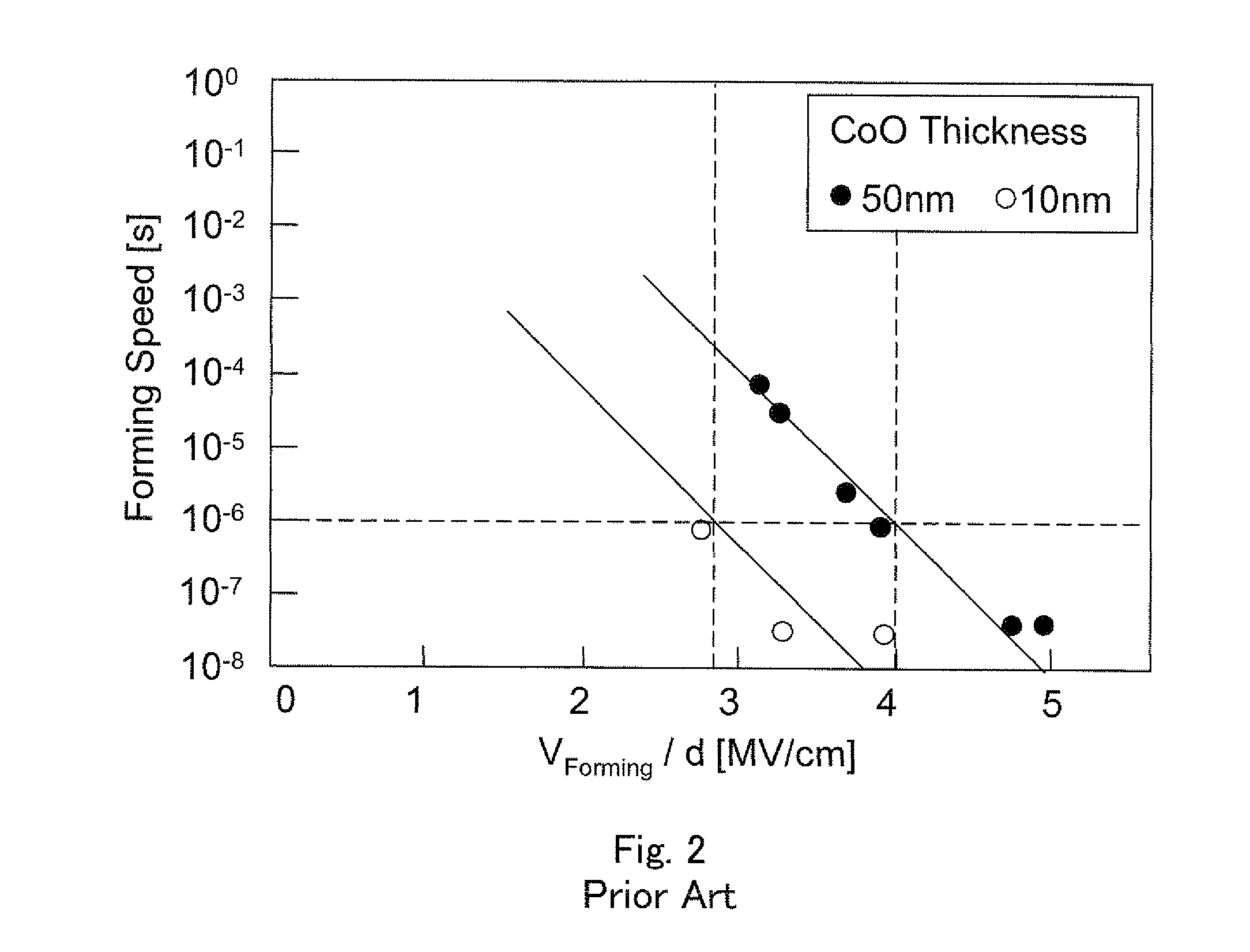
However, at the stage of fabrication of memories having a practical size using memory cells with nonvolatile variable resistive elements, it takes too much time to carry out a forming process on each memory cell of the memory, and therefore, it is urgent to shorten the forming time, from the point of view of efficiency in mass production.

Method used


Image

  • Control circuit for forming process on nonvolatile variable resistive element and control method for forming process
  • Control circuit for forming process on nonvolatile variable resistive element and control method for forming process
  • Control circuit for forming process on nonvolatile variable resistive element and control method for forming process

Examples


first embodiment

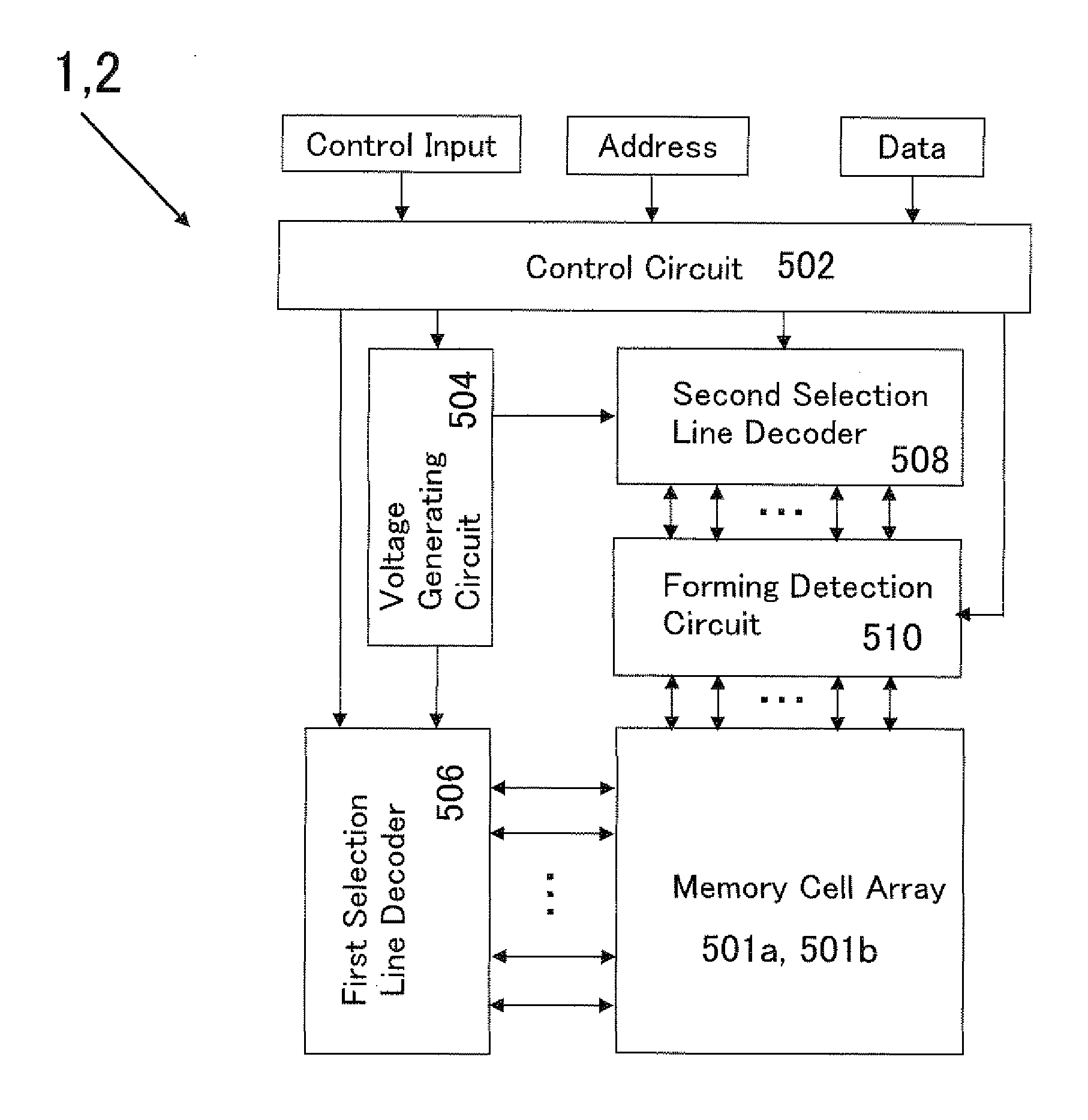
[0044]FIG. 5 is a circuit diagram showing the configuration of the nonvolatile semiconductor memory device (hereinafter referred to as “device 1 of the present invention”) according to an embodiment of the present invention. The present memory device is formed of a memory cell array 501a, a control circuit 502, a voltage generating circuit 504, a first selection line decoder 506, a second selection line decoder 508 and a forming detection circuit 510.

[0045]The memory cell array 501a is shown in the equivalent circuit diagram of FIG. 3, and has memory cells including a nonvolatile variable resistive element and a selection transistor that are aligned in a matrix. Here, the nonvolatile variable resistive elements are nonvolatile variable resistive elements with two terminals having electrodes at both ends of a variable resistor, and electrical stress is applied across the two terminals of the nonvolatile variable resistive elements when a forming process is carried out, so that the va...

second embodiment

[0068]The nonvolatile semiconductor memory device according to another embodiment of the present invention (hereinafter referred to as “device 2 of the present invention”) has the structure shown in the circuit diagram in FIG. 5, as does the device 1 of the present invention according to the first embodiment, but the structure of the memory cell array is different from that in the device 1 of the present invention. The device 3 of the present invention is formed of a memory cell array 501b, a control circuit 502, a voltage generating circuit 504, a first selection line decoder 506, a second selection line decoder 508 and a forming detection circuit 510, and the structure and operation of the control circuit 502, the voltage generating circuit 504 and the forming detection circuit 510 are exactly the same as in the device 1 of the present invention, and therefore, the descriptions are not repeated.

[0069]The memory cell array 501b is shown in the equivalent circuit diagram in FIG. 10,...


PUM


Abstract

A nonvolatile semiconductor memory device can carry out a forming process simultaneously on the nonvolatile variable resistive elements of memory cells and make the forming time shorter. The nonvolatile semiconductor memory device has a forming detection circuit provided between the memory cell array and the second selection line (bit line) decoder. The forming detection circuit detects the completion of the forming process for memory cells by measuring the fluctuation in the potential of second selection lines or the current flowing through the second selection lines when applying a voltage pulse for a forming process through the second selection lines simultaneously to the memory cells on which a forming process is to be carried out connected to the same first selection line (word line), and prevents a voltage from being applied to the second selection lines connected to the memory cells where the completion of the forming process is detected.

Description

CROSS REFERENCE TO RELATED APPLICATION[0001]This Nonprovisional application claims priority under 35 U.S.C. §119(a) on Patent Application No. 2009-061771 filed in Japan on 13 Mar., 2009 the entire contents of which are hereby incorporated by reference.BACKGROUND OF THE INVENTION[0002]1. Field of the Invention[0003]The present invention relates to a control circuit for a forming process on a nonvolatile semiconductor memory device for storing information using nonvolatile variable resistive elements for efficiently carrying out the forming process required for the operation of the elements as nonvolatile variable resistive elements, as well as a control method for a forming process.[0004]2. Description of the Related Art[0005]In recent years, various device structures, such as FeRAMs (ferroelectric RAMS), MRAMs (magnetic RAMS) and OUMs (ovonic unified memories) have been proposed as next-generation nonvolatile random access memories (NVRAMs) which make high speed operation possible a...

Claims


Application Information

Patent Timeline
Patent Type & Authority Applications(United States)
IPC IPC(8): G11C11/00
CPCG11C13/0007G11C13/0011G11C13/0064G11C13/0069H01L27/24G11C2213/34G11C2213/72G11C2213/79G11C2013/0083H10B63/00
Inventor KAWABATA, SUGURUISHIHARA, KAZUYAOHTA, YOSHIJI
Owner SHARP KK
Learn More