Diffusive light reflectors with polymeric coating

a light reflector and polymer coating technology, applied in the direction of synthetic resin layered products, woven fabrics, metal layered products, etc., can solve the problems of limited forming of metal-plexifilamentary film-fibril sheet laminates, affecting the light distribution effect, and reducing the efficiency of fixtures, etc., to achieve the effect of improving the light distribution

Inactive Publication Date: 2010-09-23
TEATHER ERIC WILLIAM HEARN
View PDF27 Cites 14 Cited by
  • Summary
  • Abstract
  • Description
  • Claims
  • Application Information

AI Technical Summary

Benefits of technology

[0015]It would be desirable to provide a diffuse light reflector for use in lighting fixtures formed from coil steel or aluminum which would take advantage of the high diffuse light reflectance of plexifilamentary film-fibril sheet while avoiding the limitations of the sheet in this application. It would also be desirable to have the high diffuse reflectance...

Problems solved by technology

It is desirable to maximize the light reflected by the reflector and minimize the light absorbed by the reflector, as any light absorbed is unusable, thereby decreasing the efficiency of the fixture.
Forming a metal-plexifilamentary film-fibril sheet laminate is limited by the surface properties ...

Method used


Image

  • Diffusive light reflectors with polymeric coating
  • Diffusive light reflectors with polymeric coating
  • Diffusive light reflectors with polymeric coating

Examples


example 1

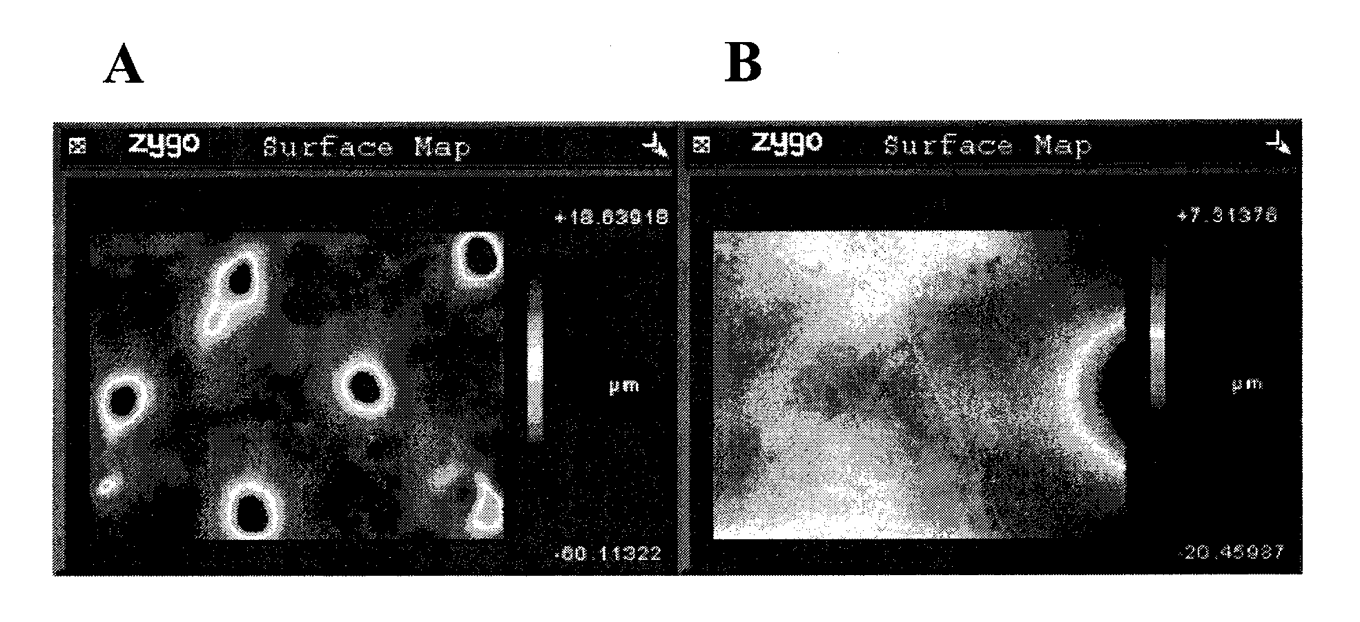
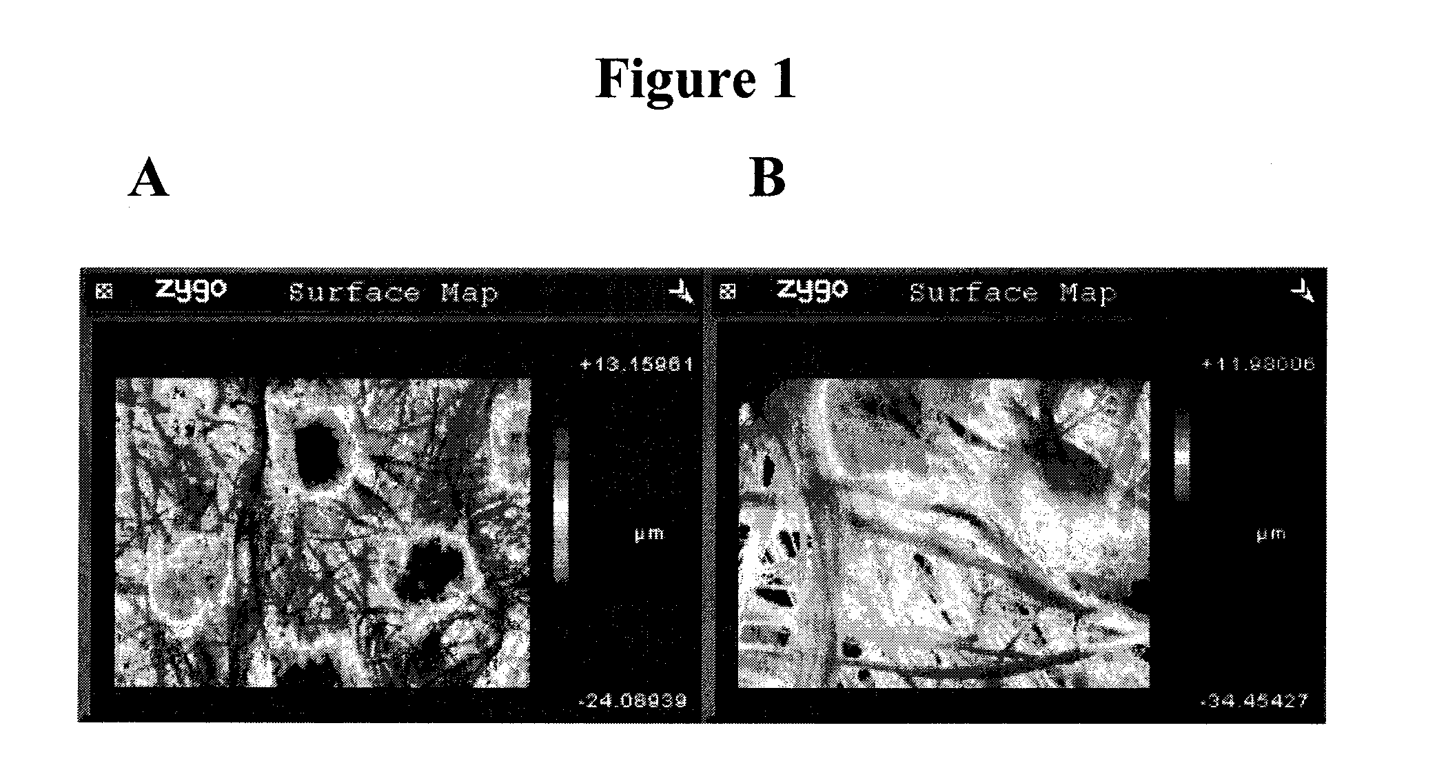
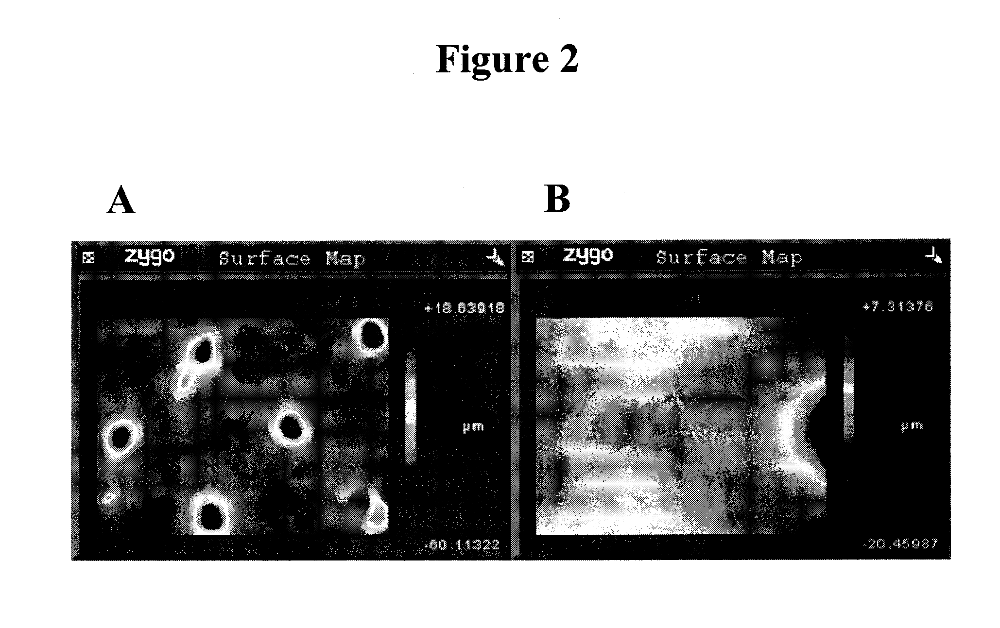
[0043]Low density polyethylene combined with 14% TiO2 pigment by weight was extruded onto Tyvek® 1070D plexifilamentary film-fibril sheet to achieve a coating weight of 22 grams per square meter. The extruded layer was passed over a matte-finish chilled roll imparting a random micro-finish topography. The total thickness of the coated sheet was measured at 215 microns. As a result of coating, the reflectance of the sheet increased from 93.5% (uncoated sheet) to 96% (coated sheet). The coating partially obscured the fiber pattern of the sheet resulting in a more uniform appearance. Machine oils put onto the surface were easily cleaned off without a visible stain. A sample of the coated sheet was exposed to 110° C. in a convection oven for 12 hours and suffered a 2% loss in reflectance. An additional sample was exposed to 80° C. in a convection oven for 12 hours without reflectance loss.

example 2

[0044]55% low density polyethylene, 33% high density polyethylene and 12% TiO2 pigment by weight were combined and extruded onto Tyvek® 1070D plexifilamentary film-fibril sheet to achieve a coating weight of 35 grams per square meter. The extruded layer was passed over a matte-finish chilled roll imparting a random micro-finish topography. The total thickness of the coated sheet was measured at 228 microns. The reflectance increased as a result of coating from 93.5% to 96.5%. As in Example 1, the coating partially obscured the fiber pattern for a more uniform appearance, and oils on the surface were easily cleaned off without a visible stain. The coated sheet was exposed to 110° C. in an oven for 12 hours without reduction in reflectance.

example 3

[0045]EMA resin (Lotryl® 20MA08) combined with 7% TiO2 was extruded onto the reverse (previously uncoated) side of the material from Example 1 to achieve a coating weight of 22 grams per square meter and passed over a matte-finish chilled roll for a matte finish. The total sheet thickness was measured at 218 microns. The reflectance of the EMA-coated side was measured as 94%. The EMA-coated side was then applied to 0.026″ (0.66 mm) thick unpainted cold rolled steel preheated to 80° C. The reflectance of the laminate face (side not bonded to metal) was measured at 95.7%


PUM

PropertyMeasurementUnit
Fractionaaaaaaaaaa
Percent by massaaaaaaaaaa
Thicknessaaaaaaaaaa

Abstract

A diffuse light reflector is disclosed for use in lighting fixtures including luminaires, light boxes, displays, signage, daylighting applications, and the like. The reflector includes a light reflective nonwoven and a polymer layer that enhances reflectivity. The reflector can be laminated to coil steel or aluminum and can be formed in metal coil or sheet forming operations. The polymer layer can be easily cleaned of machine oils from the metal forming operations.

Description

[0001]This application claims benefit to Provisional Application No. 61 / 210,674 filed Mar. 20, 2009, the entire contents of which are specifically incorporated herein by reference.BACKGROUND OF THE INVENTION[0002]1. Field of the Invention[0003]The invention relates to a polymeric coated diffuse light reflector for use in light reflective articles such as lighting fixtures and the like in which diffuse light reflectance is desired.[0004]2. Description of Related Art[0005]Reflectors are used in numerous types of lighting fixtures to maximize the usable light, thus increasing the lighting efficiency. Maximization is achieved through a combination of reflecting and redirecting light generated by the lamp in a desired direction, and minimizing the light absorbed by the reflector. This is particularly important when the light fixture design includes a light cavity in which light rays are redirected multiple times within the cavity before exiting the light fixture as usable light. Fixtures...

Claims


Application Information

Patent Timeline
IPC IPC(8): F21V7/00F21V3/00
CPCB32B15/08B32B15/20B32B27/12B32B27/30B32B27/32F21V7/00B32B27/36F21V7/22G02B5/0808A01G1/001B32B27/34B32B5/022B32B7/12B32B15/18B32B27/08B32B27/18B32B27/308B32B27/38B32B2262/0253B32B2264/108B32B2270/00B32B2307/408B32B2307/41B32B2307/416B32B2307/538B32B2307/71B32B2410/00B32B2457/20B32B2590/00F21V7/24F21V7/28Y10T442/2598Y10T442/2861Y10T442/674Y10T442/678
Inventor TEATHER, ERIC WILLIAM HEARN
Owner TEATHER ERIC WILLIAM HEARN
Why Eureka
Try Eureka