
Secondary battery including one-way exhaust valve

a technology of secondary batteries and exhaust valves, which is applied in the direction of cell components, sustainable manufacturing/processing, and final product manufacturing, etc., can solve the problems of difficult to reliably operate in the corresponding region under a high pressure condition requiring the exhaust of gas, the safety of the battery is seriously deteriorated, and the gas exhaust function is difficult to achieve. achieve the effect of preventing the introduction of external gas or moisture into the battery and easy and convenient treatment of the gas exhaust valv

Active Publication Date: 2010-09-23
LG ENERGY SOLUTION LTD
View PDF4 Cites 19 Cited by
  • Summary
  • Abstract
  • Description
  • Claims
  • Application Information

AI Technical Summary

Benefits of technology

The present invention provides a plate-shaped secondary battery with a one-way exhaust valve that allows internal high-pressure gas to be exhausted out of the battery while preventing external gas from being introduced. This improves the efficiency and safety of the battery. The one-way exhaust valve is mounted at a sealed portion of the battery case and is constructed in various forms to prevent leakage of electrolyte or moisture. The battery case is made of a laminate sheet and the electrode assembly is sealed by thermally welding the sealed portion. The one-way exhaust valve is not thick and does not affect the overall thickness of the battery. The one-way exhaust valve includes a first film, a porous film, a variable film, and a second film. The technical effects of the invention include improved efficiency and safety of the battery, prevention of leakage of electrolyte or moisture, and easy control of gas exhaust.

Problems solved by technology

Also, it is required for the sealing portions of the battery case to release the sealability, when high pressure is generated in the battery due to the abnormal operation of the battery, such as continuous charge and discharge for a long period of time or application of high temperature to the battery, to exhaust gas out of the battery case.
However, the sealing function and the gas exhaust function are opposite action mechanisms, and therefore, it is difficult to effectively achieve both the sealing function and the gas exhaust function.
In this connection, there has been restrictively proposed only a structure for releasing the sealed portion when high pressure is generated in a plate-shaped secondary battery; however, there has been not proposed a structure for exhausting pressurized gas out of a plate-shaped secondary battery while maintaining the sealability of the secondary battery.
However, experiments carried out by the inventors of the present invention revealed that the adhesive force of the sealed portion where the gas exhaust mechanism is formed is small, and therefore, moisture continuously permeates into the battery cell through the sealed portion where the gas exhaust mechanism is formed and an electrolyte continuously leaks from the battery cell through the sealed portion where the gas exhaust mechanism is formed, even during the normal operation of the battery, whereby the safety of the battery is seriously deteriorated.
In consideration of a fact that the size of the non-welded part and the size of the adhesive strength must be precisely controlled within a specific range due to the above-mentioned problems, the disclosed technology has a fundamental problem in that it is difficult for the corresponding region to be reliably operated under a high pressure condition requiring the exhaust of gas.
However, the above-mentioned technologies do not secure the sealability and operational reliability of the battery.
However, the one-way gas exhaust structure of these technologies is applicable to devices that are not seriously affected by moisture introduced into the devices, and therefore, the one-way gas exhaust structure is not structurally applicable to a plate-shaped secondary battery.
In conclusion, no attempts have been made to apply the one-way gas exhaust structure to the plate-shaped secondary battery.

Method used


Image

  • Secondary battery including one-way exhaust valve
  • Secondary battery including one-way exhaust valve
  • Secondary battery including one-way exhaust valve

Examples


Embodiment Construction

[0047]Now, a preferred embodiment of the present invention will be described in detail with reference to the accompanying drawings. It should be noted, however, that the scope of the present invention is not limited by the illustrated embodiment.

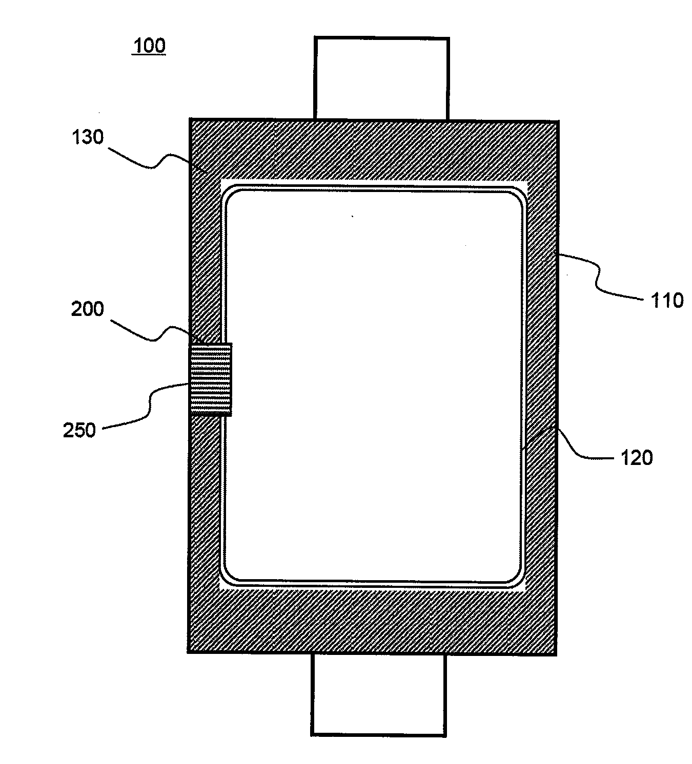
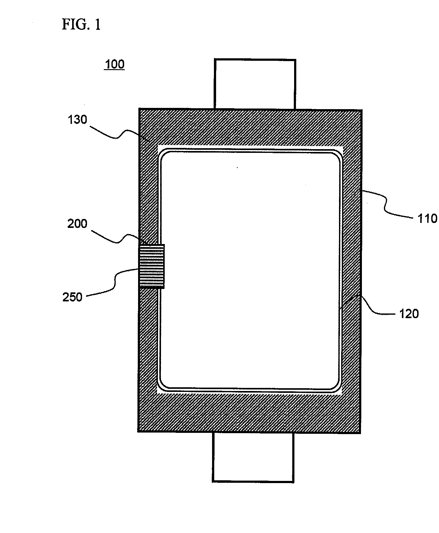
[0048]FIG. 1 is a plan view illustrating a pouch-shaped secondary battery according to a preferred embodiment of the present invention. The secondary battery of FIG. 1 is approximately identical to a conventional pouch-shaped secondary battery, which is being generally used, and therefore, only the characteristics of the present invention will be described hereinafter.

[0049]Referring to FIG. 1, the secondary battery 100 is constructed in a structure in which a sealed portion 130 is formed along the outer circumference of an electrode assembly receiving part 120 of a battery case 110, made of an aluminum laminate sheet, and a one-way exhaust valve 200 is mounted at the sealing portion 130.

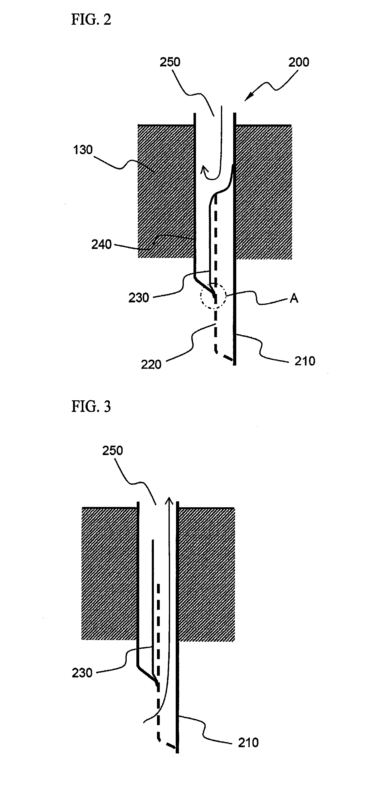
[0050]The one-way exhaust valve 200 is constructed in ...


PUM

PropertyMeasurementUnit
thicknessaaaaaaaaaa
flexibleaaaaaaaaaa
elasticaaaaaaaaaa

Abstract

Disclosed herein is a plate-shaped secondary battery constructed in a structure in which an electrode assembly of a cathode / separator / anode structure is mounted in a battery case, and the battery case is sealed by thermal welding, wherein the secondary battery has at least one valve (one-way exhaust valve), having a small thickness, mounted at a sealed portion, formed at the outer circumference of an electrode assembly receiving part of the battery case, for allowing internal high-pressure gas to be exhausted out of a battery cell and preventing external gas from being introduced into the battery cell. The secondary battery according to the present invention has the effect of effectively exhausting internal high-pressure gas generated during the abnormal operation of the battery, such as overcharge, out of the battery case, while maintaining the sealability of the battery case, thereby simultaneously improving the efficiency and safety of the battery.

Description

FIELD OF THE INVENTION[0001]The present invention relates to a secondary battery including a one-way exhaust valve, and, more particularly, to a plate-shaped secondary battery constructed in a structure in which an electrode assembly of a cathode / separator / anode structure is mounted in a battery case, and the battery case is sealed by thermal welding, wherein the secondary battery has at least one valve, having a small thickness, mounted at a sealed portion, formed at the outer circumference of an electrode assembly receiving part of the battery case, for allowing internal high-pressure gas to be exhausted out of a battery cell and preventing external gas from being introduced into the battery cell.BACKGROUND OF THE INVENTION[0002]As mobile devices have been increasingly developed, and the demand of such mobile devices has increased, the demand of secondary batteries has also sharply increased as an energy source for the mobile devices. Among them is a lithium secondary battery havi...

Claims


Application Information

Patent Timeline
Patent Type & Authority Applications(United States)
IPC IPC(8): H01M2/12H01M50/105H01M50/119H01M50/121H01M50/124H01M50/186
CPCH01M2/0207H01M2/0275H01M2/0277H01M2/0285H01M2/0287H01M2/08Y02E60/122H01M2/1235H01M10/0436H01M10/052H01M10/0583H01M10/0585H01M2/1229Y02E60/10H01M50/124H01M50/342H01M50/325Y02P70/50H01M50/105H01M50/121H01M50/186H01M50/119
Inventor YANG, SEUNG-JINCHOI, JEONG HEELEE, HANHORYU, JI HEON
Owner LG ENERGY SOLUTION LTD
Learn More