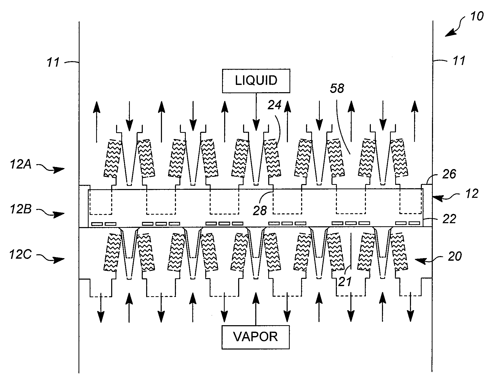
[0010]The present invention is associated with the discovery of improved contacting stages, which include one or more individual, co-current contacting modules, for carrying out vapor-liquid contacting. Co-current contacting modules of particular interest are those in which (i) downwardly flowing liquid, exiting a downcomer that receives liquid from a duct of a receiving pan of a superior stage, and (ii) upwardly flowing vapor, exiting a
demister outlet of an inferior stage, are both discharged into co-current flow channels. The invention therefore applies to co-current vapor-liquid contacting devices with non-parallel stages and structures for transferring liquid from
one stage to the next inferior stage without reducing liquid handling capability. Such devices provide an efficient usage of
column space for fluid flow and contacting, in order to achieve high capacity, high efficiency, and low pressure drop.
[0011]The fabrication of such contacting stages is improved using one or more structural enhancements, preferably a combination of enhancements, to achieve significantly improved rigidity between the various parts and thereby avoid movement / separation of these parts. This reduces the possibility of
fluid leakage across, and consequently vapor and / or liquid bypassing of, the contacting stage, which can ultimately reduce the efficiency of the vapor-liquid separation that a given co-current contacting apparatus is designed to achieve. Particular aspects of the invention pertain to the manner in which parts of the contacting stage, including the demisters, downcomers, and receiving pans, are installed and / or secured. Significant benefits in the installation and the resulting
structural integrity of contacting stages, as described herein, can result from a number of structural enhancements acting in combination.
[0012]Aspects of the invention therefore relate to high capacity and high efficiency co-current vapor-liquid contacting apparatuses for use in
fractionation columns and other vapor-liquid contacting processes. Such apparatuses generally comprise a plurality of contacting stages, each comprising a number of parts or elements that must be fabricated such that they can be installed in a
confined space, for example in a cylindrical vessel of a contacting apparatus, and in a secure manner covering a cross section of the vessel. The invention is therefore broadly directed to improved contacting stages for co-current contacting apparatuses, in which the downcomers, demisters, and receiving pans are secured in a sealing or substantially sealing manner that minimizes or prevents bypassing, or passage of vapor and / or liquid across the contacting stage without contact between these two phases.
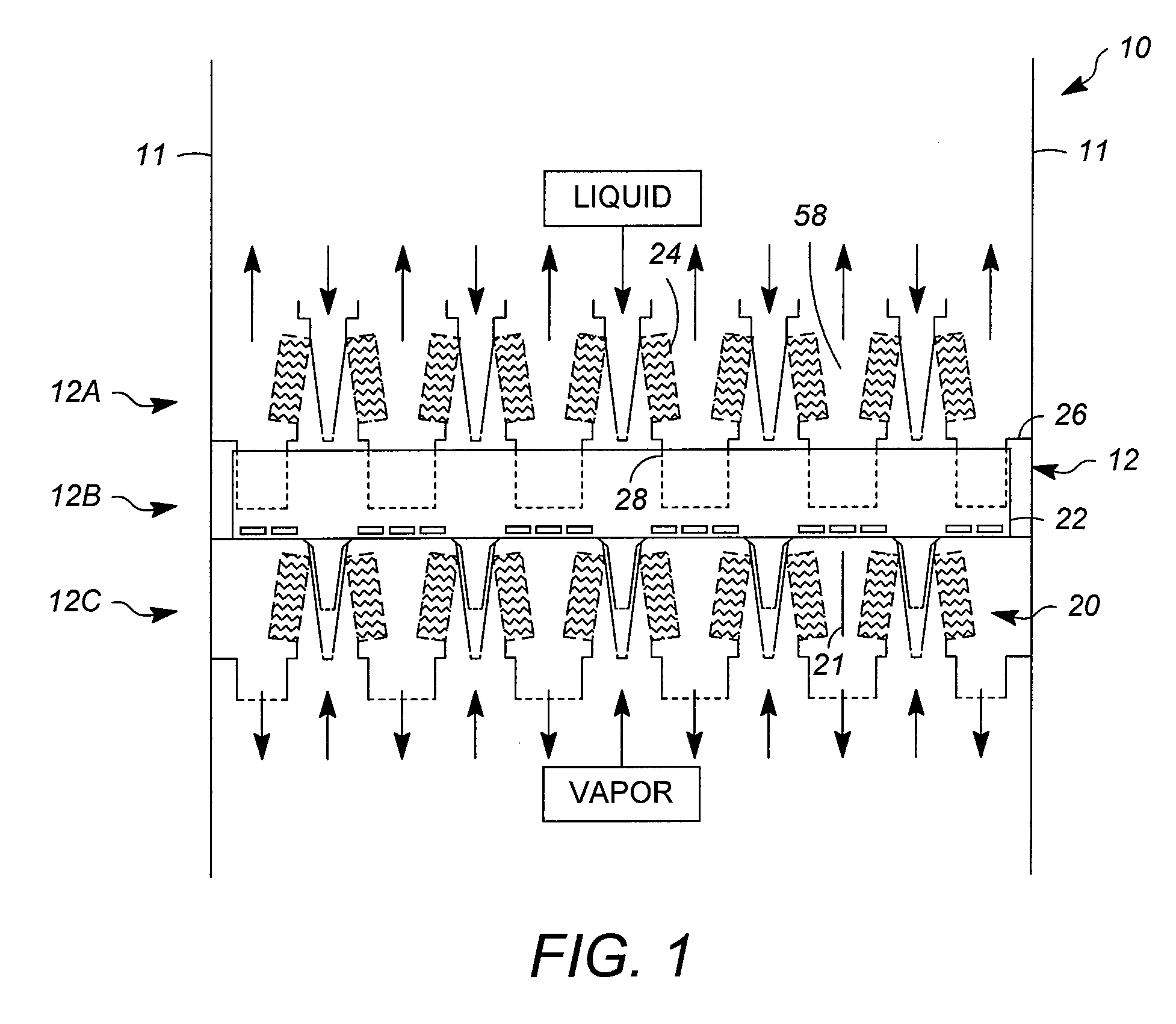
[0019]Further aspects of the invention relate to securing the bottom sections of the
demister units, in a manner that, as discussed above with respect to the top sections, reduces or eliminates bypassing of vapor and / or liquid as it passes through a contacting stage. One manner of installing of the
demister units involves initially placing bottom sections of the demister units in a matching or compatible section, such as a support rail. In other embodiments, however, a support angle extending below bottom surfaces of the demister units allows them to be installed securely even without a support rail, such that the support rail becomes an optional feature. In this case, the support angle rests on a vertically extending lip of a receiving pan.
[0024]The contacting stages can have any of structural enhancements discussed above, alone or in combination, which improve their integrity and performance. Particular structural enhancements are directed to providing secure attachments between top and bottom sections of the demister units and, respectively, the receiving pan and adjacent wall sections of the downcomer. With respect to the top sections, these attachments include the use of connecting angles extending over and covering upper portions of the connecting flanges of the demister units and adjacent wall sections of the downcomer. With respect to the bottom sections, these attachments include the use of support angles extending below bottom surfaces of the demister units. Other structural enhancements, which can be used alone or in combination with these, include those described above which can connect adjacent demister units through abutting, interconnecting side plates and which can connect the ends of demister rows to opposite side ends of the downcomer.

