Contacting stages for co-current contacting apparatuses

a technology of contact stage and contact apparatus, which is applied in the direction of separation process, combustion air/fuel air treatment, liquid degasification, etc., can solve the problems of reducing the efficiency of vapor-liquid separation, and achieve the effects of reducing liquid handling capability, high efficiency and high capacity

Active Publication Date: 2011-09-20
UOP LLC
View PDF20 Cites 9 Cited by
  • Summary
  • Abstract
  • Description
  • Claims
  • Application Information

AI Technical Summary

Benefits of technology

[0010]The present invention is associated with the discovery of improved contacting stages, which include one or more individual, co-current contacting modules, for carrying out vapor-liquid contacting. Co-current contacting modules of particular interest are those in which (i) downwardly flowing liquid, exiting a downcomer that receives liquid from a duct of a receiving pan of a superior stage, and (ii) upwardly flowing vapor, exiting a demister outlet of an inferior stage, are both discharged into co-current flow channels. The invention therefore applies to co-current vapor-liquid contacting devices with non-parallel stages and structures for transferring liquid from one stage to the next inferior stage without reducing liquid handling capability. Such devices provide an efficient usage of column space for fluid flow and contacting, in order to achieve high capacity, high efficiency, and low pressure drop.
[0011]The fabrication of such contacting stages is improved using one or more structural enhancements, preferably a combination of enhancements, to achieve significantly improved rigidity between the various parts and thereby avoid movement / separation of these parts. This reduces the possibility of fluid leakage across, and consequently vapor and / or liquid bypassing of, the contacting stage, which can ultimately reduce the efficiency of the vapor-liquid separation that a given co-current contacting apparatus is designed to achieve. Particular aspects of the invention pertain to the manner in which parts of the contacting stage, including the demisters, downcomers, and receiving pans, are installed and / or secured. Significant benefits in the installation and the resulting structural integrity of contacting stages, as described herein, can result from a number of structural enhancements acting in combination.
[0012]Aspects of the invention therefore relate to high capacity and high efficiency co-current vapor-liquid contacting apparatuses for use in fractionation columns and other vapor-liquid contacting processes. Such apparatuses generally comprise a plurality of contacting stages, each comprising a number of parts or elements that must be fabricated such that they can be installed in a confined space, for example in a cylindrical vessel of a contacting apparatus, and in a secure manner covering a cross section of the vessel. The invention is therefore broadly directed to improved contacting stages for co-current contacting apparatuses, in which the downcomers, demisters, and receiving pans are secured in a sealing or substantially sealing manner that minimizes or prevents bypassing, or passage of vapor and / or liquid across the contacting stage without contact between these two phases.
[0019]Further aspects of the invention relate to securing the bottom sections of the demister units, in a manner that, as discussed above with respect to the top sections, reduces or eliminates bypassing of vapor and / or liquid as it passes through a contacting stage. One manner of installing of the demister units involves initially placing bottom sections of the demister units in a matching or compatible section, such as a support rail. In other embodiments, however, a support angle extending below bottom surfaces of the demister units allows them to be installed securely even without a support rail, such that the support rail becomes an optional feature. In this case, the support angle rests on a vertically extending lip of a receiving pan.
[0024]The contacting stages can have any of structural enhancements discussed above, alone or in combination, which improve their integrity and performance. Particular structural enhancements are directed to providing secure attachments between top and bottom sections of the demister units and, respectively, the receiving pan and adjacent wall sections of the downcomer. With respect to the top sections, these attachments include the use of connecting angles extending over and covering upper portions of the connecting flanges of the demister units and adjacent wall sections of the downcomer. With respect to the bottom sections, these attachments include the use of support angles extending below bottom surfaces of the demister units. Other structural enhancements, which can be used alone or in combination with these, include those described above which can connect adjacent demister units through abutting, interconnecting side plates and which can connect the ends of demister rows to opposite side ends of the downcomer.

Problems solved by technology

This reduces the possibility of fluid leakage across, and consequently vapor and / or liquid bypassing of, the contacting stage, which can ultimately reduce the efficiency of the vapor-liquid separation that a given co-current contacting apparatus is designed to achieve.

Method used


Image

  • Contacting stages for co-current contacting apparatuses
  • Contacting stages for co-current contacting apparatuses
  • Contacting stages for co-current contacting apparatuses

Examples


Embodiment Construction

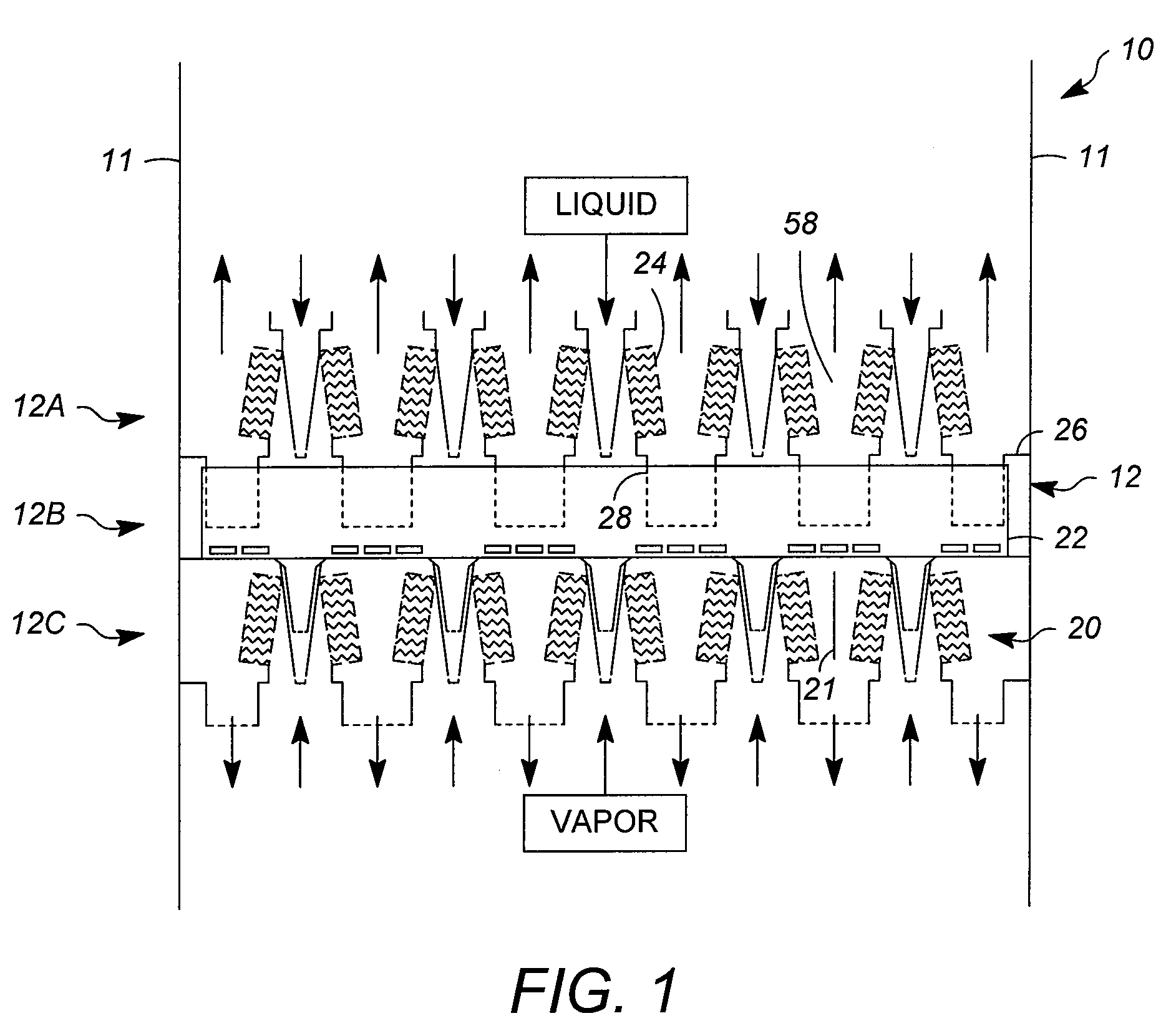
[0041]FIG. 1 illustrates a co-current vapor-liquid contacting apparatus according to the present invention, comprising stages within a vessel 10. The vessel 10 may be for example a distillation column, absorber, direct contact heat exchanger, or other vessel used to conduct vapor-liquid contacting. The vessel 10 contains contacting stages 12 and optional collector / distributors. A fractionation or distillation column typically contains from about 10 to about 250 or more contacting stages 12. The design of contacting modules 20 of these stages may be essentially uniform throughout the column, but it may also vary, for example, to accommodate changes in fluid flow rates in different parts of the column. For simplicity, only three contacting stages, namely upper 12A, middle 12B, and lower 12C contacting stages, are shown in FIG. 1.

[0042]It is understood that an apparatus such as a distillation column may contain several sections, with each section having numerous contacting stages. Also...


PUM

PropertyMeasurementUnit
angleaaaaaaaaaa
support angleaaaaaaaaaa
angleaaaaaaaaaa

Abstract

Improved contacting stages for carrying out vapor-liquid contacting are described. Particular aspects are directed to co-current vapor-liquid contacting devices with non-parallel contacting stages that provide an efficient usage of column space for fluid flow and contacting, in order to achieve high capacity, high efficiency, and low pressure drop. The fabrication of such contacting stages is improved using one or more structural enhancements, preferably a combination of enhancements, to achieve easy installation and significantly improved rigidity between the various parts and thereby avoid movement / separation of these parts. This reduces the possibility of fluid leakage across, and consequently vapor and / or liquid bypassing of, the contacting stage.

Description

FIELD OF THE INVENTION[0001]The invention relates to contacting stages for apparatuses for performing vapor-liquid contacting such as in fractional distillation or other mass and / or heat transfer operations. The invention more specifically relates to improvements in the construction of such contacting stages for better structural integrity and ease of installation.DESCRIPTION OF RELATED ART[0002]Vapor-liquid contacting devices, such as fractionation trays and packings, are employed to perform a wide variety of separations, particularly in the petroleum and petrochemical industries. Fractionation trays, for example, are used for separating hydrocarbons into fractions having a similar relative volatility or boiling point. These fractions include crude oil-derived products of petroleum refining and petrochemical processing, such as naphtha, diesel fuel, LPG, and polymers. In some cases, trays are used to separate specific compounds from others of the same chemical or functional class, ...

Claims


Application Information

Patent Timeline
Patent Type & Authority Patents(United States)
IPC IPC(8): B01D3/22B01F3/04
CPCB01D3/324B01D3/32B01D3/20C10G31/00C10G11/00B01J10/00
Inventor HELDWEIN, THOMAS C.AGNELLO, JOSEPHMUCK, AARON J.XU, ZHANPINGNOWAK, BRIAN J.
Owner UOP LLC
Why Eureka
Try Eureka