Distributing power to an integrated circuit
- Summary
- Abstract
- Description
- Claims
- Application Information
AI Technical Summary
Benefits of technology
Problems solved by technology
Method used
Image
Examples
Embodiment Construction
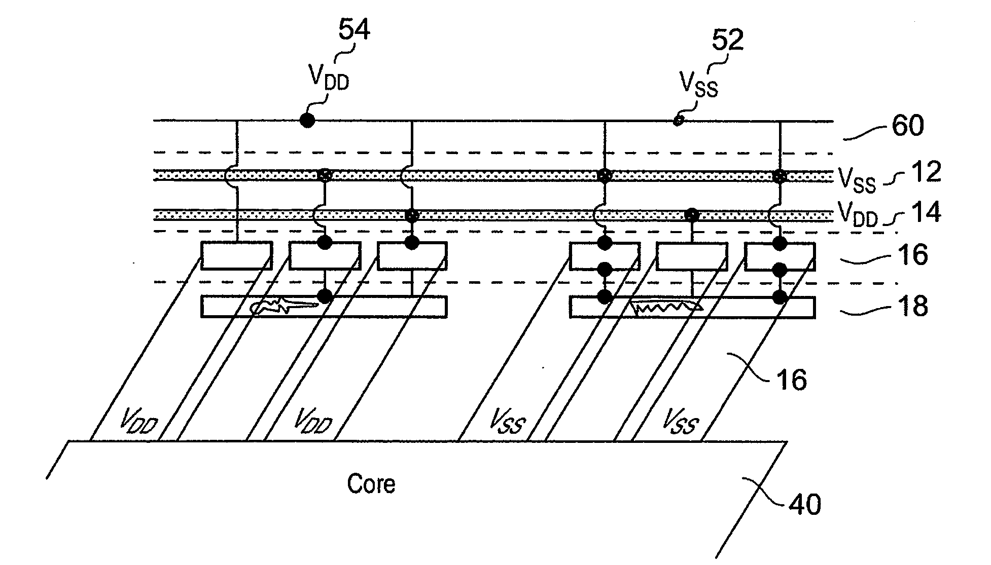
[0043]FIG. 2 shows an integrated circuit 30 that comprises a core 40 and an input / output loop 50 that comprises power cells 52 and 54 and the input / output cell 56. Power cell 52 is connected to a low voltage power supply VSS, while power cell 54 is connected to a high level voltage supply VDD. Each of these cells are a width w wide which is the pitch of the device and is the minimum width for providing bonding of a wire. In many integrated circuits nowadays this is the determining factor in size and for this reason the core 40 lies well within this input / output loop.
[0044]The power cells 52 and 54 have several layers and FIG. 3 shows one of these cells schematically in cross section. There is a top layer which is the bonding layer 60 to which the wires are bonded. There is then the layer that the power rails lie in. These are rails 12 and 14 that carry VSS and VDD around the loop of the cell. The next layer down is the layer providing the metallisation contacts that take the power f...
PUM
 Abstract
Description
Claims
Application Information
 - R&D
- Intellectual Property
- Life Sciences
- Materials
- Tech Scout
- Unparalleled Data Quality
- Higher Quality Content
- 60% Fewer Hallucinations
Browse by: Latest US Patents, China's latest patents, Technical Efficacy Thesaurus, Application Domain, Technology Topic, Popular Technical Reports.
© 2025 PatSnap. All rights reserved.Legal|Privacy policy|Modern Slavery Act Transparency Statement|Sitemap|About US| Contact US: help@patsnap.com


