
Optical pickup device, optical information device, computer, optical disk player, car navigation system, optical disk recorder, and optical disk server

Active Publication Date: 2010-09-30
PANASONIC CORP
View PDF10 Cites 8 Cited by
  • Summary
  • Abstract
  • Description
  • Claims
  • Application Information

AI Technical Summary

Benefits of technology

[0019]In view of the above, it is an object of the invention to provide an optical pickup device, an optical information device, a computer, an optical disc player, a car navigation system, an optical disc recorder, and an optical disc server that enable to prevent damage or performance degradation of an optical component constituting a second optical system, and suppress degradation of the recording / reproducing performance of the optical pickup device.
[0021]In the above arrangement, there is no likelihood that the first light beam having the first wavelength may be incident into the optical component constituting the second optical system. This enables to prevent damage or performance degradation of the optical component constituting the second optical system, and suppress degradation of the recording / reproducing performance of the optical pickup device.

Problems solved by technology

In providing compatibility, it is difficult to secure a long operating distance, as in an objective lens for use in DVD or CD, while securing a large numerical aperture i.e. 0.85 for the objective lens.
In use of the optical pickup device having the above arrangement, irradiation of blue laser light may lower the transmittance of the optical component, or affect the composition of the light transmissive member, thereby damaging the optical element.
Because of the above phenomenon, use of a resin component, as an optical component for a semiconductor laser for emitting laser light in a red wavelength band or an infrared wavelength band, may cause damage of an optical element, transmittance lowering, or wavefront aberration degradation, with the result that the recording / reproducing performance of the optical pickup device may be degraded, because generally the optical element does not have light resistance against blue light.
However, if the above measure is taken, it may be difficult or impossible to secure a light amount of a blue light beam sufficient for performing a recording / reproducing operation with respect to a multi-layered disc, or a high-speed recording / reproducing operation.
This may lower the recording / reproducing quality of the optical pickup device.

Method used


Image

  • Optical pickup device, optical information device, computer, optical disk player, car navigation system, optical disk recorder, and optical disk server
  • Optical pickup device, optical information device, computer, optical disk player, car navigation system, optical disk recorder, and optical disk server
  • Optical pickup device, optical information device, computer, optical disk player, car navigation system, optical disk recorder, and optical disk server

Examples


first embodiment

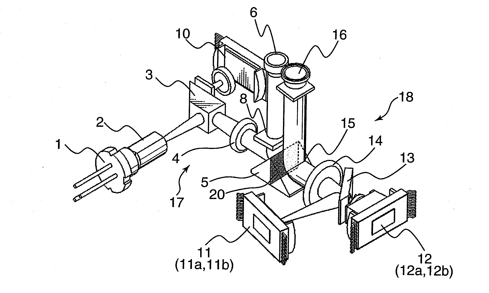
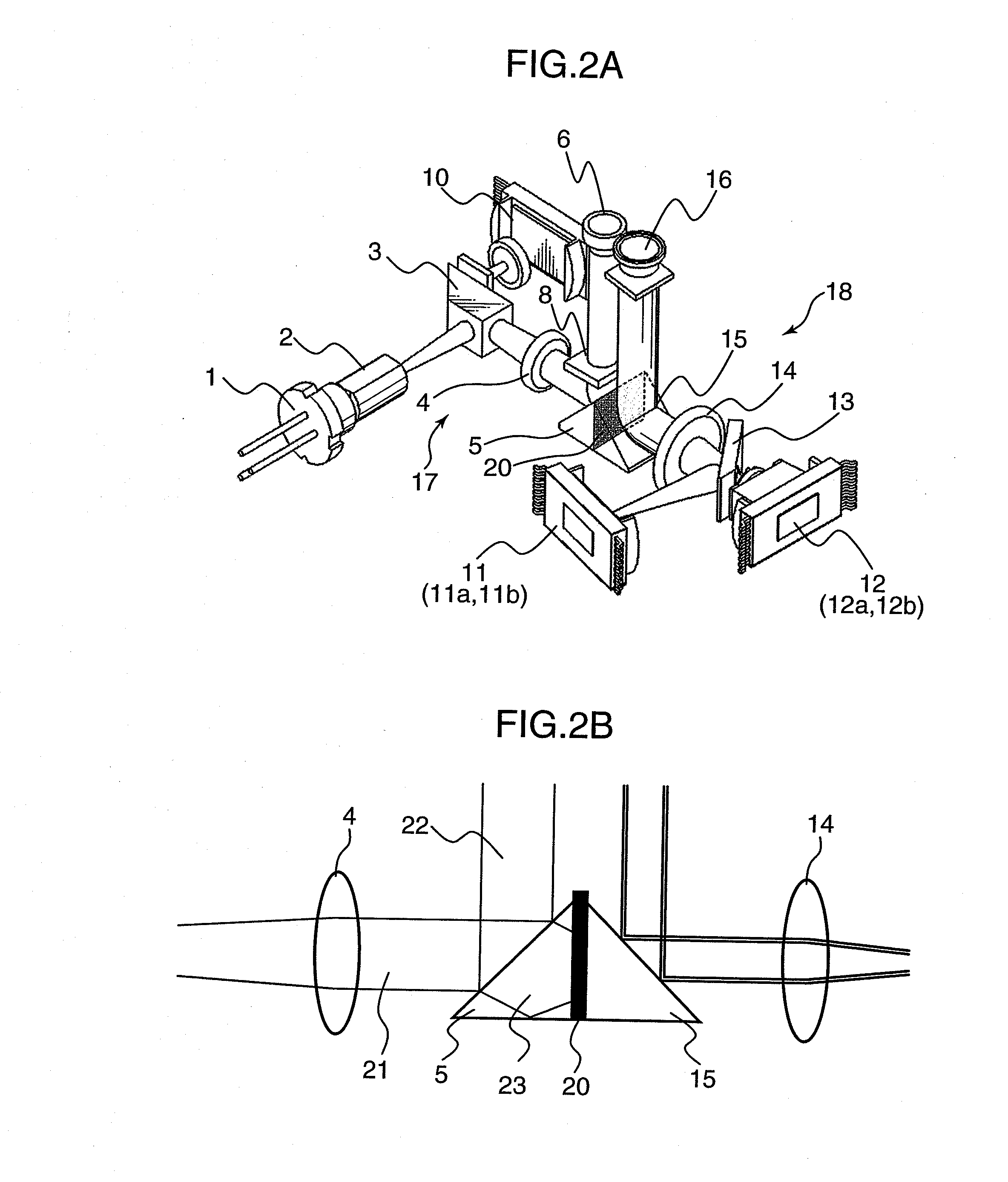
[0046]FIG. 2A is a diagram showing an example of an optical pickup device in accordance with the first embodiment.

[0047]Referring to FIG. 2A, the optical pickup device includes a first laser light source 1, a beam shape forming element 2, a beam splitter 3, a collimator lens 4, a first rise-up mirror 5, a first objective lens 6, a quarter wavelength plate 8, a first photodetector 10, a DVD integration unit 11, a CD integration unit 12, a wavelength, selective mirror 13, a collimator lens 14, a second rise-up mirror 15, a second objective lens 16, and a filter 20.

[0048]A first optical system 17 is constituted of the beam shape forming element 2, the beam splitter 3, the collimator lens 4, the first rise-up mirror 5, the first objective lens 6, and the quarter wavelength plate 8. A second optical system 18 is constituted of the wavelength selective mirror 13, the collimator lens 14, the second rise-up mirror 15, and the second objective lens 16.

[0049]The first laser light source 1 emi...

second embodiment

[0070]FIGS. 3A through 3C are enlarged side views of rise-up mirrors in optical pickup devices in accordance with the second embodiment. Elements in FIGS. 3A through 3C substantially identical or equivalent to those in FIG. 2B are indicated with the same reference numerals, and description thereof is omitted herein. The arrangement and the effect of the optical pickup devices of the second embodiment are substantially the same as the arrangement and the effect of the optical pickup device of the first embodiment shown in FIG. 2A.

[0071]Referring to FIG. 3A, a filter 20 for absorbing light of the first wavelength λ1 is disposed on a reflection surface of a first rise-up mirror 5. In this arrangement, preferably, the filter 20 may be operable to absorb or reflect light of the first wavelength λ1, and have a transmittance of 5% or less with respect to the light of the first wavelength λ1. With use of the filter 20 having the above characteristics, there is no or less likelihood that lea...

third embodiment

[0086]FIGS. 5A through 5D are enlarged side views of rise-up mirrors in optical pickup devices in accordance with the third embodiment. Elements in FIGS. 5A through 5D substantially identical or equivalent to those in FIG. 2B are indicated with the same reference numerals, and description thereof is omitted herein. The arrangement and the effect of the optical pickup devices of the third embodiment are substantially the same as the arrangement and the effect of the optical pickup device of the first embodiment shown in FIG. 2A.

[0087]In this embodiment, a first rise-up mirror 5 and a second rise-up mirror 15 are each constituted of a flat plate mirror, in place of a prism. A flat plate mirror is advantageous in fabricating a part, as compared with a prism mirror. In use of a flat plate mirror, however, leaked light 23 transmitting through the first rise-up mirror 5 is radiated from a surface of the first rise-up mirror 5 opposite to a reflection surface thereof in a direction paralle...


PUM


Abstract

An object of the invention is to prevent damage or performance degradation of an optical component constituting a second optical system, and suppress degradation of the recording / reproducing performance of an optical pickup device. A first laser light source 1 emits a first light beam having a first wavelength. A first optical system 17 guides the first light beam to be emitted from the first laser light source 1 to a first optical disc. A DVD integration unit 11 emits a second light beam having a second wavelength different from the first wavelength. A second optical system 18 guides the second light beam to be emitted from the DVD integration unit 11 to a second optical disc different from the first optical disc in recording density. A filter 20 is disposed at a position capable of blocking incidence of an unwanted light beam having the first wavelength derived from the first optical system 17 into an optical component constituting the second optical system 18 to block the first light beam having the first wavelength.

Description

TECHNICAL FIELD[0001]The present invention relates to an optical pickup device, an optical information device, a computer, an optical disc player, a car navigation system, an optical disc recorder, and an optical disc server for recording information in an optical disc and / or reproducing information from an optical disc.BACKGROUND ART[0002]There are proposed a variety of kinds of recording media for recording or storing digital audio data, an image, a moving image, and a document file / data file created with use of a computer or a like device. An optical disc is known among the variety of kinds of recording media. A DVD (Digital Versatile Disk) has a high density and a large capacity, as compared with a conventional CD (Compact Disc), and has been spread as a recording medium for use in a recording device in place of a VTR (Video Tape Recorder). In recent years, development of a next-generation optical disc having a higher recording density, with use of a blue semiconductor laser, ha...

Claims


Application Information

Patent Timeline
IPC IPC(8): G11B20/00G11B7/00G11B7/125G11B7/135
CPCG11B7/08582G11B7/1275G11B2007/0006G11B7/1381G11B7/1362
Inventor TANAKA, TOSHIYASUKOMMA, YOSHIAKI
Owner PANASONIC CORP
Features
  • Generate Ideas
  • Intellectual Property
  • Life Sciences
  • Materials
  • Tech Scout
  • Unparalleled Data Quality
  • Higher Quality Content
  • 60% Fewer Hallucinations
Learn More