Transmission apparatus

Inactive Publication Date: 2010-09-30
HITACHI LTD
View PDF6 Cites 5 Cited by
  • Summary
  • Abstract
  • Description
  • Claims
  • Application Information

AI Technical Summary

Benefits of technology

[0014]Data determination can be made without amplifying a data signal at a maximum transfer rate, processing of a noise component of the data signal is difficult to effect upon amplification. As a result of further decrease in a transmission rate of the data signal to be

Problems solved by technology

However, if the higher reference voltage or the lower reference voltage is set to a signal composed of identical bits “0” in succession, or “1” in succession, such as 0000 . . . 1111, or 1111 . . . 0000, there occurs inconvenience in that it is not possible to detect a signal wherein “0” and “1” are alternately repeated, such as 010101 . . . 01, or 101010 . . . 10 even though a data transfer rate is the same.
As a result, there occurs a problem that a transmission signal cannot be determined if the transmission signal is at a voltage level between the higher reference voltage, and the

Method used


Image

  • Transmission apparatus
  • Transmission apparatus
  • Transmission apparatus

Examples


Embodiment Construction

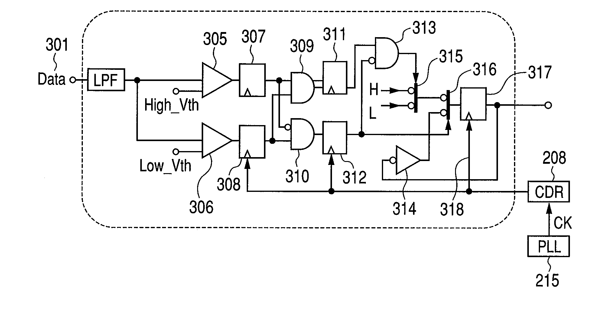
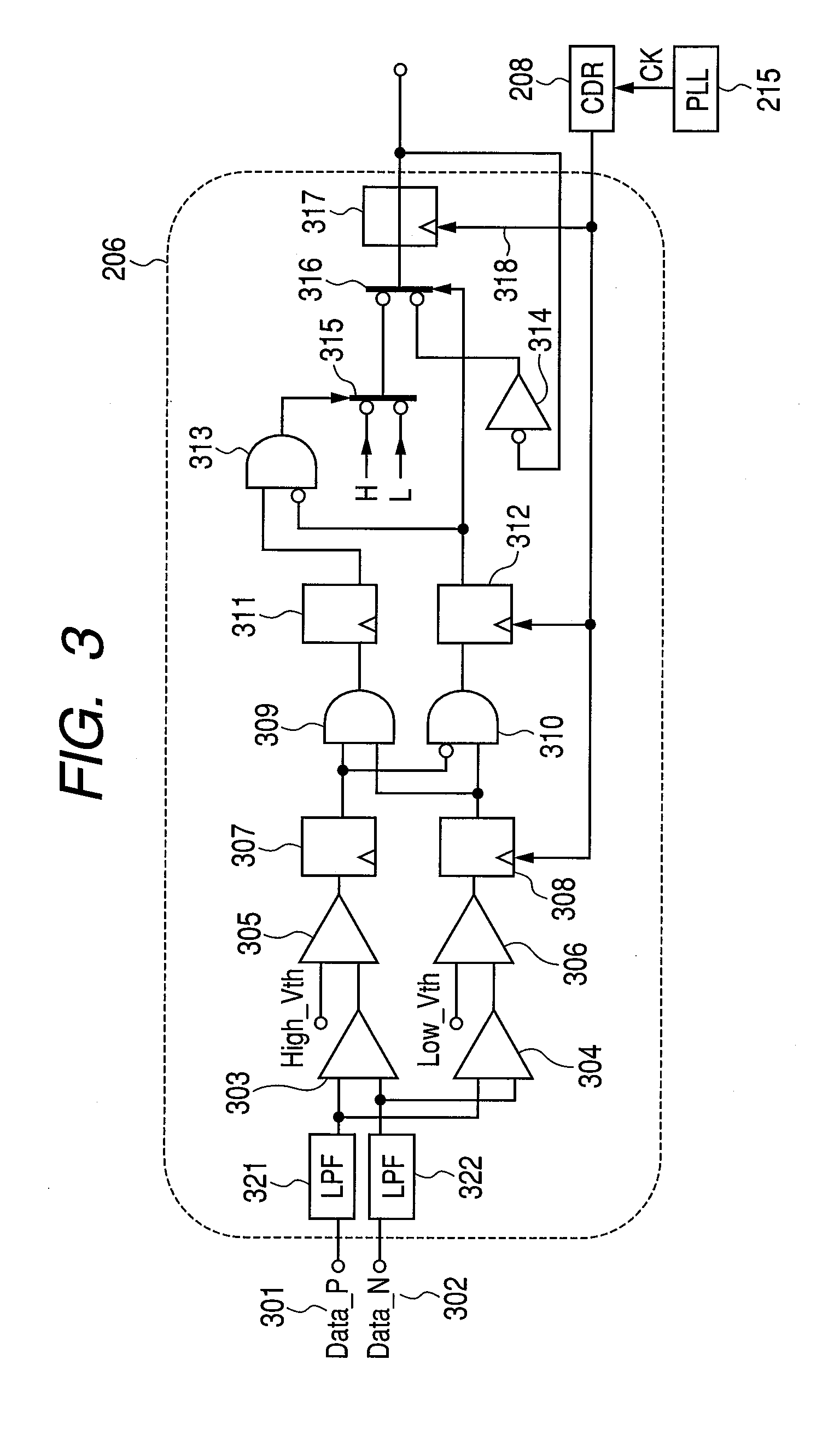
[0024]The invention is described in detail hereinafter on the basis of an embodiment thereof. A transmission method whereby the feed forward equalizer within an integrated circuit on a transmission side is combined with the decision feedback equalizer within an integrated circuit on a receiving side can be applied to a transmission system for execution of high-speed data transfer between devices.

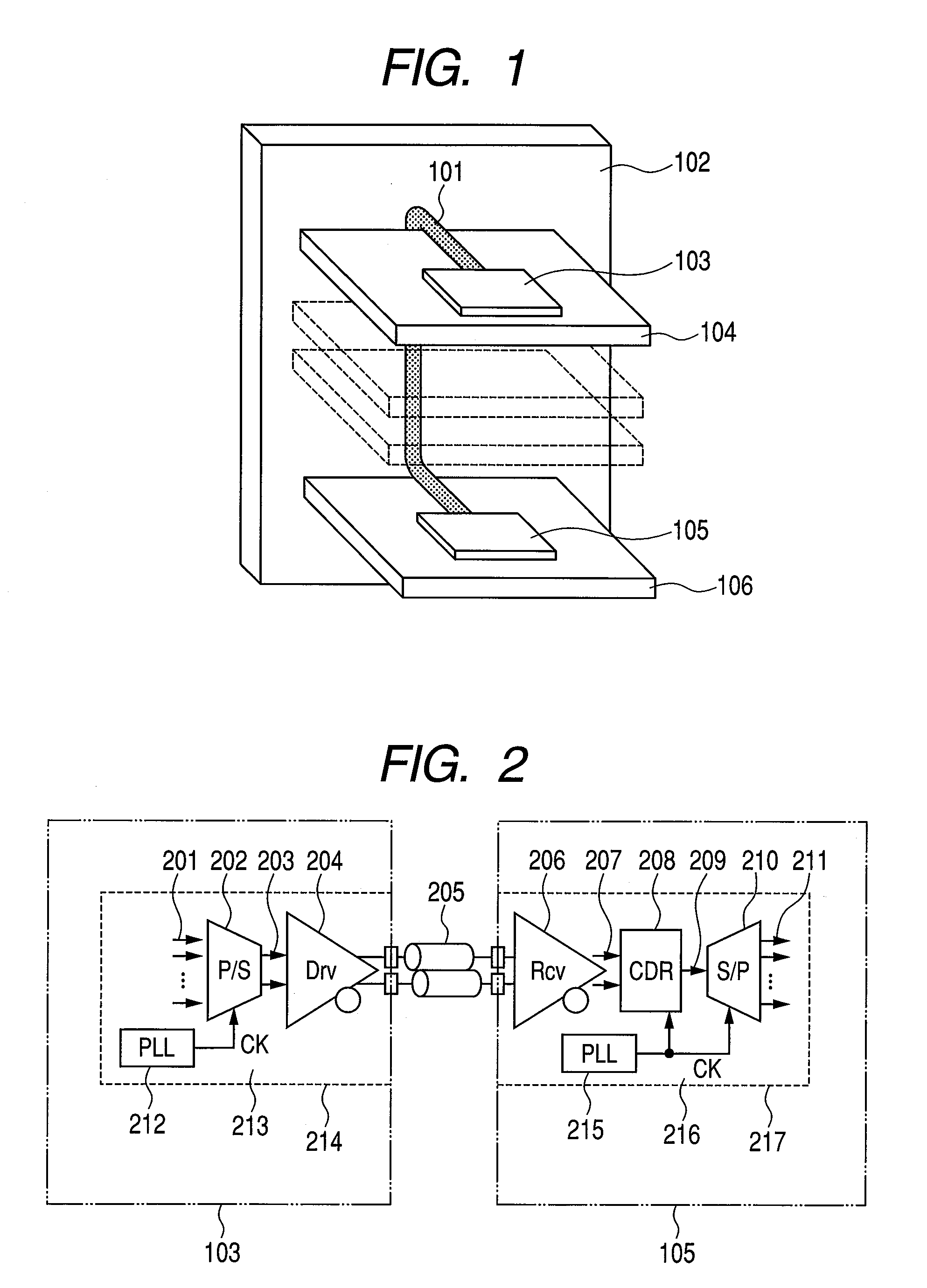
[0025]FIG. 1 is a block diagram showing a high-speed data transfer system between devices. The high-speed data transfer system between devices, includes a signal interconnect 101, a backplane 102, an integrated circuit (LSI) 103, a daughter board 104. An integrated circuit (LSI) 105 is mounted on the daughter board 106.

[0026]The signal interconnect is for connecting the integrated circuit (LSI) 103 to the integrated circuit (LSI) 105, and data transfer is effected via the signal interconnect 101. The signal interconnect is also called generally a transmission line. The backplane is a kind of...


PUM


Abstract

A differential amplifier stage under a band design whereby a data signal at a maximum transfer rate among received waveforms is subjected to attenuation upon passing through a transmission line is not amplified, and a signal at a transfer rate half the maximum transfer rate is amplified. If it is determined that a signal whose amplitude is larger in value than a high reference voltage, the signal is determined as a signal “1” while if smaller in value than a low reference voltage, the signal is determined as a signal “0”. If the first amplitude detector detects that the amplitude of the signal is smaller in value than the high reference voltage, and the second amplitude detector detects that the amplitude of the signal is larger in value than the low reference voltage, the present signal is determined as an inverting signal of an immediately preceding signal.

Description

CLAIM OF PRIORITY[0001]The present application claims priority from Japanese patent application JP 2009-071136 filed on Mar. 24, 2009, the content of which is hereby incorporated by reference into this application.FIELD OF THE INVENTION[0002]The present invention relates to a transmission apparatus, and more particularly, to a technology for use in high-speed data transfer between devices, effective in speeding up a data transfer.BACKGROUND OF THE INVENTION[0003]In connection with high-speed data transfer between devices, a demand for high-speed long-distance transfer has lately been mounting. In the case of the high-speed data transfer, there is an increase in transmission loss in a transmission line, and a decrease in received amplitude becomes pronounced. In addition, there will be a pronounced decrease in eye aperture margin due to the effect of inter-symbol interference. Techniques such as pre-emphasis, de-emphasis, and decision feedback are well known as means for solving this...

Claims


Application Information

Patent Timeline
IPC IPC(8): H04B3/00
CPCH04B3/30H04L25/03057H04L25/0272
Inventor USHIO, YUJIMUTO, TAKASHI
Owner HITACHI LTD
Why Eureka
Try Eureka