Blade provided with a drag damper, and a rotor provided with such a blade

a technology of a blade and a damper, which is applied in the direction of propellers, propulsive elements, water-acting propulsive elements, etc., can solve the problems of difficult to balance forces while flying in translation, the oscillation of each blade about its drag axis can become coupled, and the material fatigue phenomenon is harmful to materials, so as to limit the excessive stress

Active Publication Date: 2010-09-30
EUROCOPTER
View PDF7 Cites 16 Cited by
  • Summary
  • Abstract
  • Description
  • Claims
  • Application Information

AI Technical Summary

Benefits of technology

[0044]An object of the present invention is thus to provide a blade and a rotor provided with such blades that make it possible to overcome the above-mentioned limi

Problems solved by technology

Consequently, the resultant of the aerodynamic forces exerted on a blade does not have the same value in each direction, nor even the same point of application: the fixed-end or “restrained” bending moments at the root of the blade is thus high and variable, thereby generating alternating mechanical stresses leading to a fatigue phenomenon that is harmful for the materials.
Furthermore, the resultant of the aerodynamic forces from all of the blades is no longer carried by the axis of the rotor, thereby creating a roll moment that increases with increasing speed and that can make it difficult to balance forces while flying in translation.
Nevertheless, the oscillations of each blade about its drag axis can become coupled in unstable manner with the elastic deformation modes or movements of the airframe, in particular oscillations of the helicopter while standing on the ground via its landing gear: this is the origin of the so-called “ground resonance” phenomenon that can be dangerous for the aircraft when the resonant

Method used


Image

  • Blade provided with a drag damper, and a rotor provided with such a blade
  • Blade provided with a drag damper, and a rotor provided with such a blade
  • Blade provided with a drag damper, and a rotor provided with such a blade

Examples


Embodiment Construction

[0081]Elements that are present in more than one of the figures are given the same references in each of them.

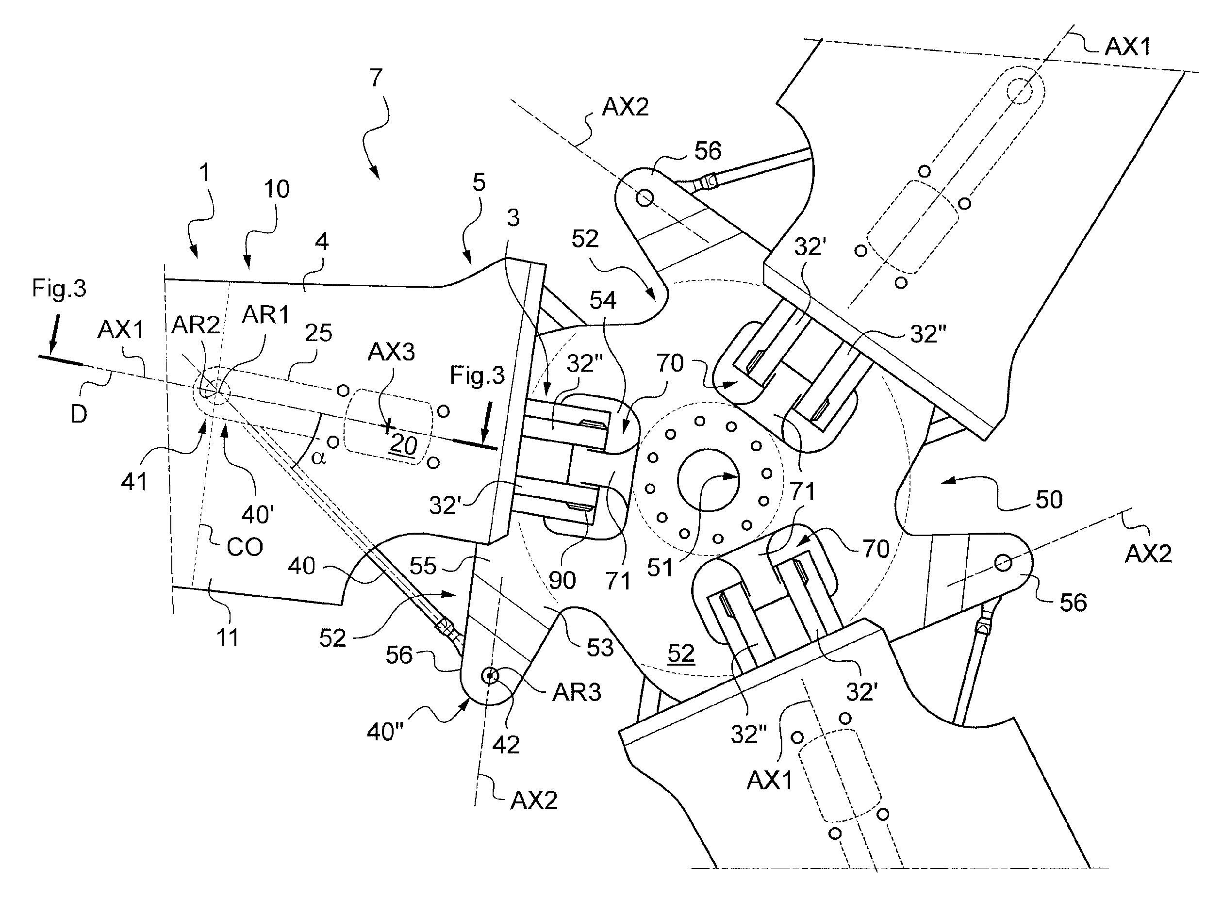
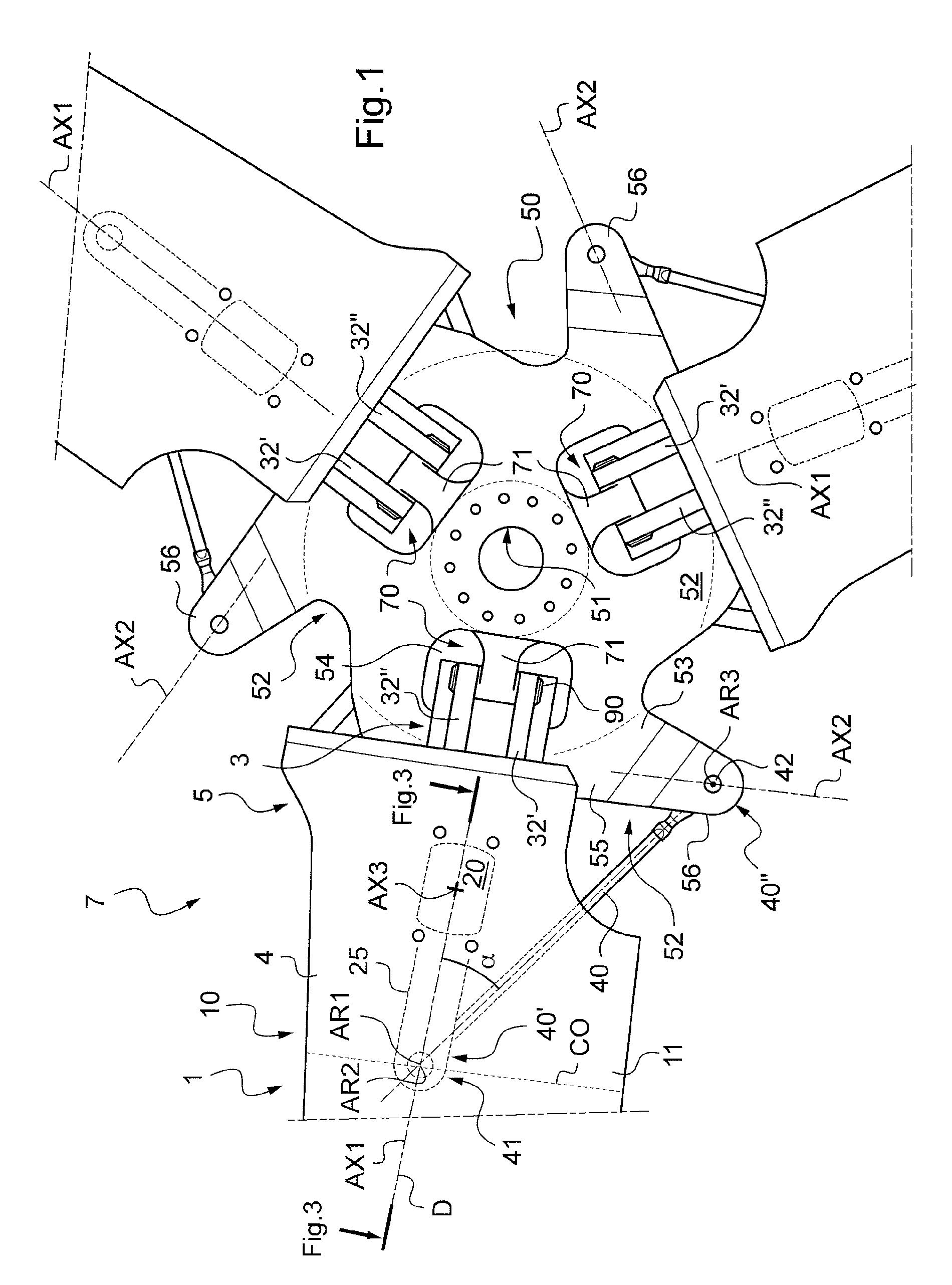
[0082]FIG. 1 shows a rotorcraft rotor 7 having three blades 1 arranged on a hub 50.

[0083]For this purpose, the hub 50 has an inner portion 51 in the form of a ring suitable for being secured to a rotor mast that is not shown in FIG. 1.

[0084]Furthermore, the hub 50 has three arms 52, i.e. one arm 52 per blade 1, distributed in equidistant manner around the periphery of the inner portion 51. Thus, each arm 52 possesses an inner zone 53 secured to the inner portion 51 of the hub 50 and a peripheral zone 55 opening out to the periphery of the hub 50.

[0085]It should be understood that the arms 52 and the inner portion 51 of the hub may constitute a single part, obtained by conventional machining, or indeed by making use of composite materials, with the hub 50 then being made as a single block.

[0086]Furthermore, each arm 52 is pierced vertically in its inner zone 53 so as to prese...


PUM


Abstract

The present invention relates to a rotorcraft blade (1) provided with at least one spar (3) and an outer covering (4), said blade (1) including a hollow sleeve (10) with a wall (11) that is provided at least with said outer covering (4) secured to said spar (3). The blade includes a rotary damper (20) provided with an inner tubular strength member (21) and an outer tubular strength member (22) that are coaxial and connected together by a ring (23) of viscoelastic material, said inner tubular strength member (21) being secured to said covering (4), and said outer tubular strength member (22) being provided with a fork (25) possessing first and second tines (26, 27) facing each other so as to be suitable for receiving a first ball joint (41) close to the pitch-variation axis (AX1) of said blade (1).

Description

FIELD OF THE INVENTION[0001]The present invention relates to a blade provided with a drag damper, and to a rotor provided with such a blade.[0002]More particularly, the invention lies in the technical field of damping drag movements of a blade.BACKGROUND OF THE INVENTION[0003]Conventionally, a rotorcraft rotor comprises a hub driven in rotation about an axis of revolution by an outlet shaft of a power transmission main gearbox, also referred to as a drive shaft, together with at least three blades fastened to the hub via appropriate hinges, in particular via respective laminated spherical abutments dedicated to each of the blades.[0004]On the assumption that each blade is fixed relative to the hub, it should be recalled that the rotor constituted in this way is a rigid rotor. While hovering, the distribution of aerodynamic forces along a blade gives rise to a bending moment distribution presenting a very large value at the root of the blade. When flying in translation, the blade tha...

Claims


Application Information

Patent Timeline
IPC IPC(8): B64C27/35
CPCB64C27/35B64C2027/4736B64C27/51
Inventor GIRARD, VINCENTMAZET, STEPHANEMETIVIER, REMIEBERHARD, ALAIN
Owner EUROCOPTER
Why Eureka
Try Eureka