Sealed secondary battery, and method for manufacturing the battery
- Summary
- Abstract
- Description
- Claims
- Application Information
AI Technical Summary
Benefits of technology
Problems solved by technology
Method used
Image
Examples
first embodiment
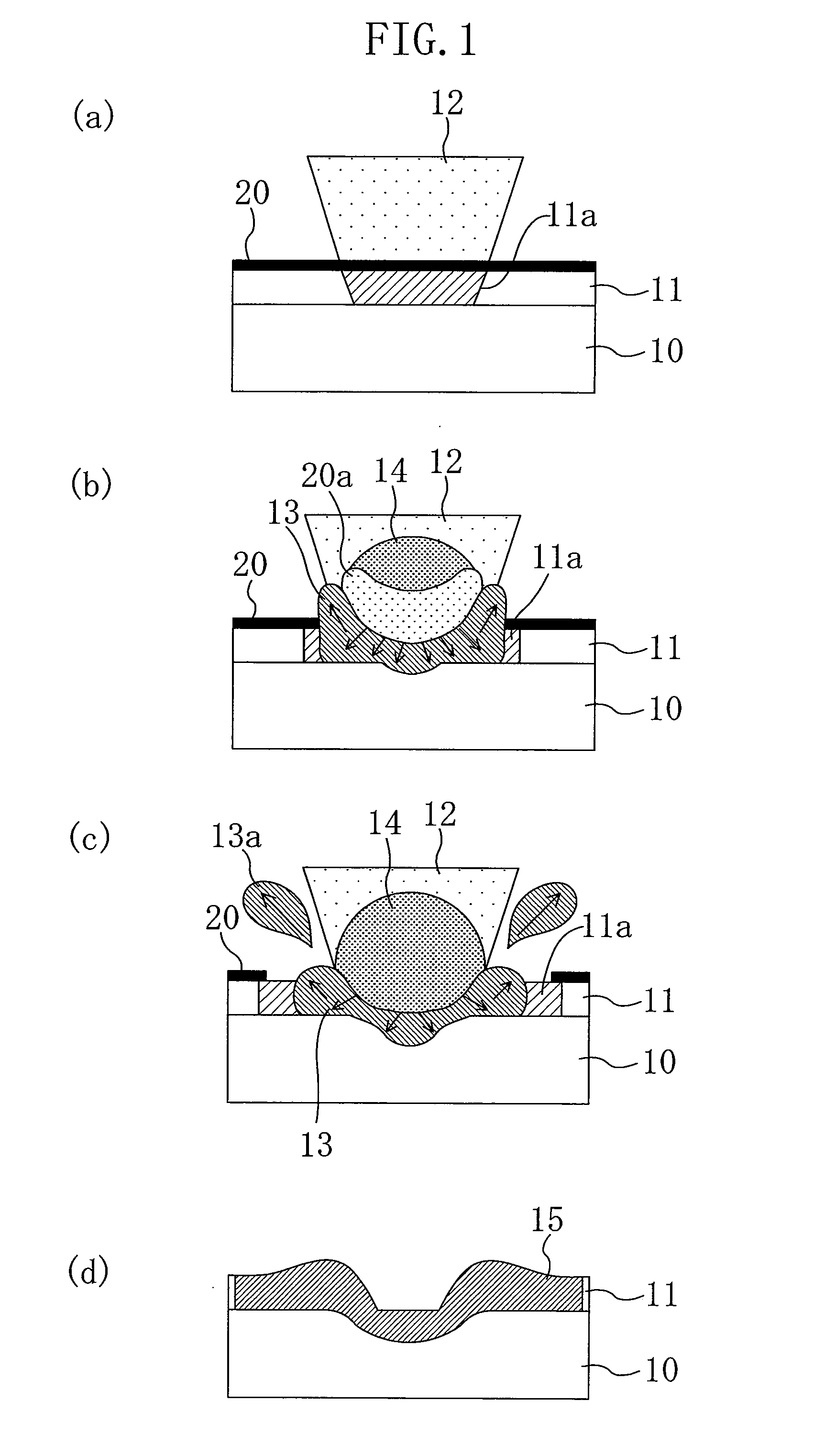
[0064]FIGS. 6(a)-6(d) are cross-sectional views schematically illustrating a process of laser-welding a lead 11 to a sealing plate 10 according to a first embodiment of the present invention.
[0065]As illustrated in FIG. 6(a), the lead 11 is irradiated with a fiber laser beam (hereinafter simply referred to as a “laser beam”) 12 with the lead 11 brought into contact with the sealing plate 10, thereby heating a laser-irradiated region 11a of the lead 11. The laser beam 12 has a spot diameter smaller than the thickness of the lead 11.
[0066]As illustrated in FIG. 6(b), the heated region 11a partially melts to form a melted portion 13, and an evaporation repulsive force of metal vapor from the melted lead 11 forms a keyhole. Then, as illustrated in FIG. 6(c), as the keyhole further grows, the melted portion 13 is also extended beyond the surface of the sealing plate 10. Thereafter, when the irradiation with the laser beam 12 is stopped, the melted portion 13 is hardened to fill the keyho...
second embodiment
[0079]The spot diameter of a fiber laser is about 1 / 10 of that of a YAG laser. Thus, the joint strength might decrease as the welding area decreases. Accordingly, a large number of welded portions are necessary for ensuring a sufficient joint strength. However, laser welding of a plurality of portions with a laser beam producing pulse oscillation causes repetitive state changes among heating, melting, and solidification, resulting in that sputtering readily occurs. In addition, some welded portions might be unstable, and as a result, a stable joint strength might not be obtained.
[0080]In view of these problems, in order to obtain a stable joint structure without occurrence of sputtering, a technique for forming a linear melted portion by performing continuous scanning with a continuously oscillating fiber laser is proposed in this embodiment. With this technique, a joint structure having a joint strength almost equal to or greater than the joint strength obtained with a YAG laser ca...
third embodiment
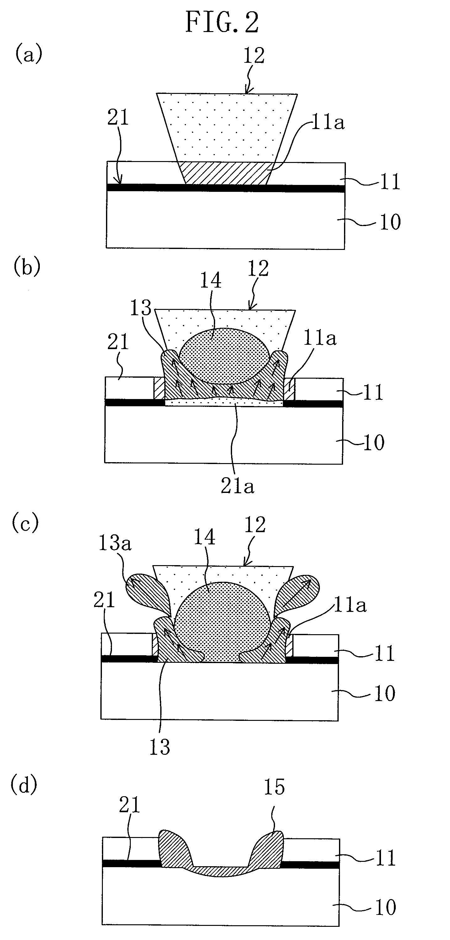
[0094]The inventors of the present invention conducted keyhole joining between a lead 11 and a sealing plate 10 with a method according to the present invention, and studied the resultant joint structure, to find out the following phenomena.
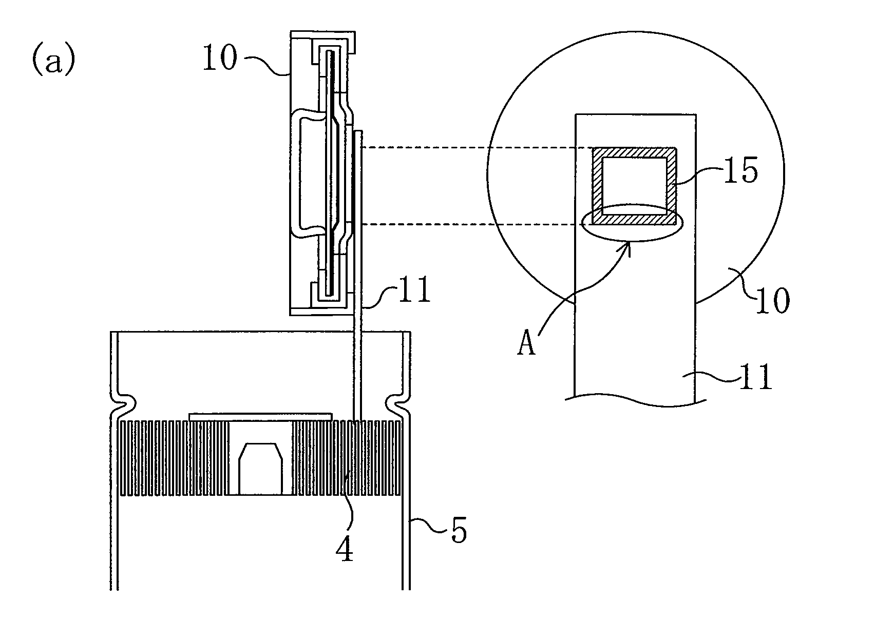
[0095]As illustrated in FIG. 7(a), an end of the lead 11 (made of aluminium foil with a thickness of 0.15 mm and a width of 4 mm) extending from an electrode group was brought into contact with the sealing plate 10 (made of an aluminium plate with a thickness of 0.1 mm in a portion welded to the lead 11, and a diameter of 16.8 mm). In this state, the lead 11 was irradiated with a laser beam having a spot diameter of 0.02 mm and a power density of 7×10⁷W / cm2, while being scanned along the width of the lead 11 at a scanning speed of 10 m / min. In this manner, laser welding was performed on the lead 11 and the sealing plate 10, and a joint structure of the resultant welded portion 15 was observed.
[0096]FIGS. 15(a)-15(d) show the results of the above-...
PUM
| Property | Measurement | Unit |
|---|---|---|
| Thickness | aaaaa | aaaaa |
| Power | aaaaa | aaaaa |
| Diameter | aaaaa | aaaaa |
Abstract
Description
Claims
Application Information
 - R&D
- Intellectual Property
- Life Sciences
- Materials
- Tech Scout
- Unparalleled Data Quality
- Higher Quality Content
- 60% Fewer Hallucinations
Browse by: Latest US Patents, China's latest patents, Technical Efficacy Thesaurus, Application Domain, Technology Topic, Popular Technical Reports.
© 2025 PatSnap. All rights reserved.Legal|Privacy policy|Modern Slavery Act Transparency Statement|Sitemap|About US| Contact US: help@patsnap.com


