Refuelable battery-powered electric vehicle

a battery-powered electric vehicle and rechargeable technology, applied in the direction of electric/hybrid propulsion, propulsion parts, process and machine control, etc., can solve the problems of fast recharge time, increased cost, and increased cost, and achieve the effect of continuous operation of electric vehicles indefinitely

Active Publication Date: 2010-09-30
SCHEUCHER KARL F
View PDF15 Cites 79 Cited by
  • Summary
  • Abstract
  • Description
  • Claims
  • Application Information

AI Technical Summary

Benefits of technology

[0027]The circuitry and control methodology described herein is applicable to use of modular energy supply systems in automobiles. For instance, the control methodology described herein may be used in connection with Lithium ion batteries used in an automobile. In this way, the batteries may be removed from the automobile and recharged at a service station and then replaced into the vehicle fully charged. The batteries may be separately removed from the automobile or they may be removed in groups. The invention as taught and described herein enables the evaluation of individual batteries and the evaluation of the energy remaining in the batteries at the time they are swapped out (exchanged) for fully charged batteries. In this way a motorist can effectively refuel his or her vehicle and proceed on his or her way without worrying about stopping to charge the batteries which is time consuming as the recharge time for Lithium ion batteries is considerable. Having the ability to quickly swap the batteries in a Lithium ion car enables the driver to get credit for the energy in his “gas” tank. In reality the teachings of the instant invention enable the driver to effectively have an “energy tank” as compared to a “gas tank.”
[0028]The present invention provides apparatus and methods for a battery electric vehicle (BEV) system utilizing hierarchical arrangements of cells, packs, and multi-pack racks along with distributed intelligence and power switching and mixing. This system solves the practical problems associated with quick exchange of modular batteries and off-vehicle recharging as an effective approach to fast BEV refueling. The system derives additional advantages including the ability to optimize vehicle energy efficiency as a function of driving range requirements and the economic flexibility for a user to purchase more or less energy at any service interval. The particular, modular approach to battery organization along with the distributed intelligence included therein facilitates continuous battery monitoring thereby yielding efficient and economic detection and correction of individual cell, pack, or module problems or failures. Further, the nature of the scalable, intelligent battery system herein described lends itself to many other applications including backup power for home and business as well as fully portable power for a growing host of applications in civilian and military arenas.
[0040]Intelligent packs for improved use in the vehicle and in the charging station.
[0054]The power supply is microprocessor controlled based on the status (voltage, current and temperature) of the inputs including the status of the back-up energy source, the status of converters and internal buses, and the status of the outputs. The microprocessor manages the back-up energy source and the overall operation of the power supply by selectively coupling system inputs, buses and outputs. Where power sources are combined in an “or” relationship, diodes or their equivalents are used to prohibit undesirable current flows. MOSFET based switches or their equivalents controlled by the microprocessor are used extensively in the selective coupling of the system inputs, buses and outputs.
[0083]It is an object of the invention to provide a power supply having I AC or DC inputs wherein at least one of those inputs is back-up energy source which may be a fuel cell rack, an atomic-powered generator rack, a Li-Ion battery rack, a NiMH battery rack, a NiCd battery rack, a lead acid battery rack, a Li-Ion polymer battery rack, or an Alkaline battery rack. It is an object to provide a microprocessor controlled intelligent power supply which effectively manages its backup power supply input.
[0088]It is an object of the invention to enable use of electric vehicles anywhere over long distances at high speeds without lengthy recharge periods as the batteries may be replaced at service stations just as a gasoline powered car is fueled at a gasoline service station.

Problems solved by technology

Unlike combustion engine generation and regenerative braking, plug-in grid replenishment is only useable when the vehicle is at rest, in the proximity of an electrical outlet, and then only practical when the vehicle is to be parked for some period of time.
Several hurdles challenge this approach, however.
The fast recharge time comes with the penalty of heavier, larger, batteries and correspondingly reduced vehicle range.
However, there are new issues or problems created in the '423 patent disclosure.
One issue is the requirements placed upon the replacement (exchange) mechanisms contemplated, those mechanisms being semi-automatic and powerful in nature.
Another issue impeding the system contemplated in the '423 patent is the broad degree of battery standardization envisioned as a preliminary condition to the use of the system.
As battery and electric drive technology advances, often in rapid fashion, a system requiring many attributes of the technology to remain fixed will be costly to update and maintain.
One can also see that a weighty cache of batteries, while needed for extended range driving, equates to excess weight in shorter excursions detracting unnecessarily from vehicle operating efficiency.
As batteries age and go through an increasing number of charge and discharge cycles they wear out.
This wear manifests itself in a decrease in battery capacity.
Although the maximum operating range of such vehicle decreases over time and is expected, the previous BEV system provides no mechanisms to allow disparately aged or charged batteries to be efficiently utilized.

Method used


Image

  • Refuelable battery-powered electric vehicle
  • Refuelable battery-powered electric vehicle
  • Refuelable battery-powered electric vehicle

Examples


Embodiment Construction

and Claims which follow hereinbelow.

BRIEF DESCRIPTION OF THE DRAWINGS

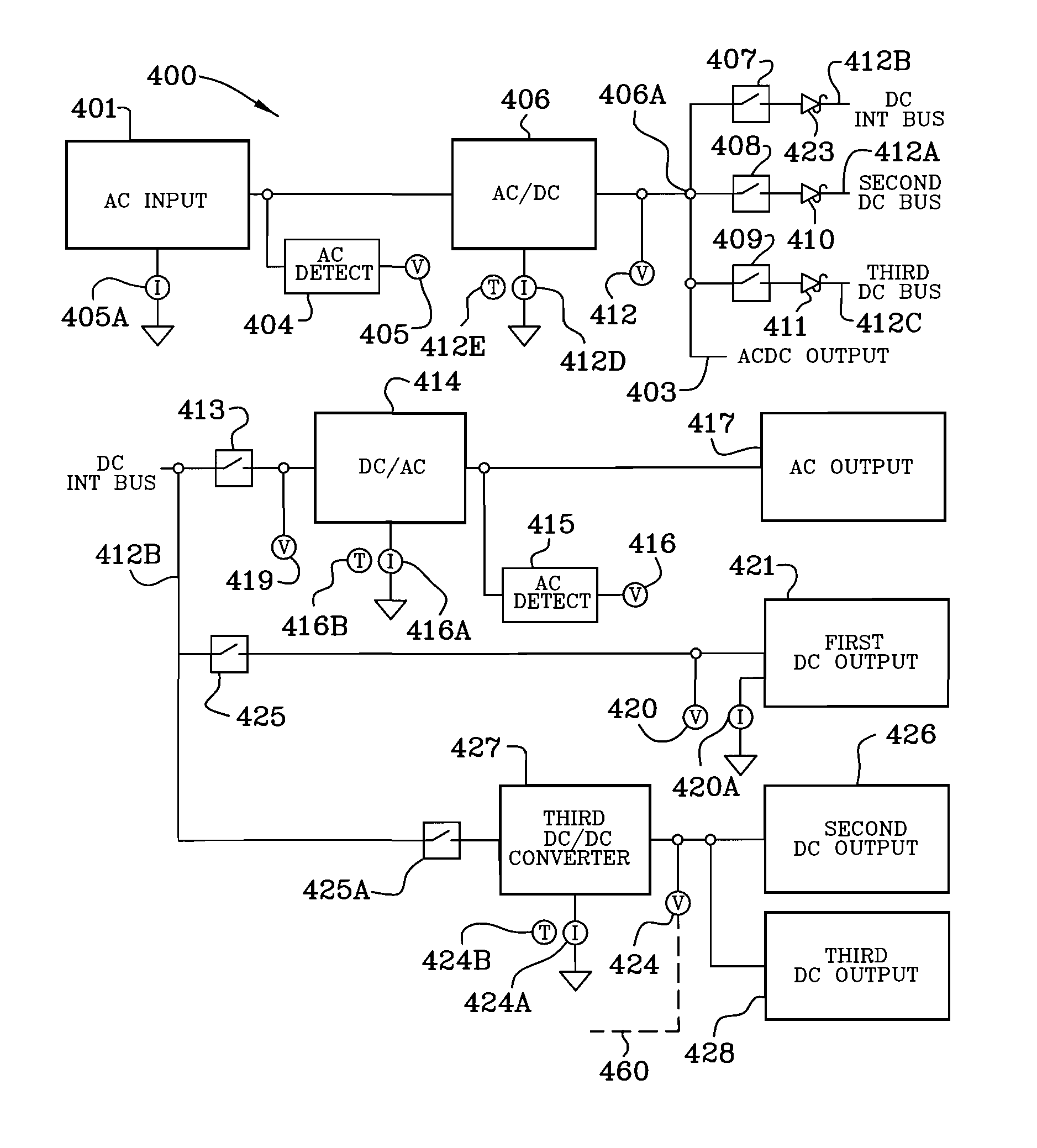
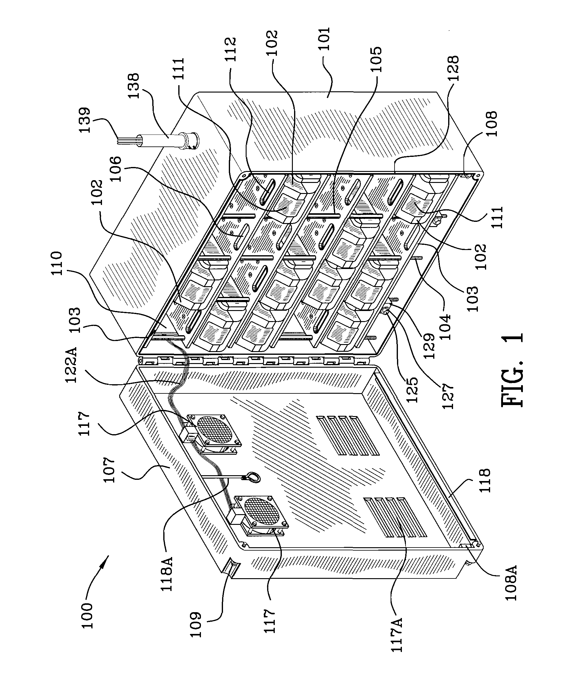
[0093]FIG. 1 is a front perspective view of the intelligent power supply device illustrating a plurality of removable cartridge energy packs in a rack.

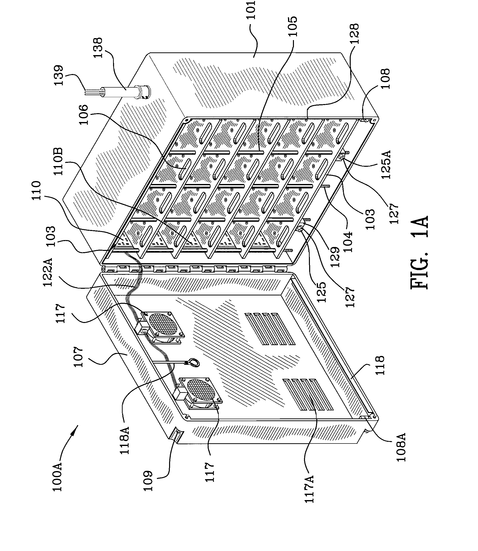
[0094]FIG. 1A is a front perspective view of the intelligent power supply device similar to FIG. 1 without the removable cartridge energy packs in the rack.

[0095]FIG. 1B is a front perspective view of the intelligent power supply device without the rack and without the removable cartridge energy packs in the rack.

[0096]FIG. 1C is a front perspective view of the rack illustrated in FIGS. 1 and 1A.

[0097]FIG. 1D is a front view of the rack partially populated with the removable cartridge energy packs in the rack.

[0098]FIG. 1E is a side view of the rack taken along the lines 1E-1E of FIG. 1D.

[0099]FIG. 1F is a side view of the rack taken along the lines 1F-1F of FIG. 1D.

[0100]FIG. 1G is an enlargement of a portion of FIG. 1D illustrating one of the removable cartridge en...


PUM

PropertyMeasurementUnit
energyaaaaaaaaaa
electrical poweraaaaaaaaaa
voltagesaaaaaaaaaa

Abstract

The electrical vehicle energy storage system permits the electric refueling of the electric vehicle just like an automobile would be refueled with gasoline at a gas station. Circuitry on board the vehicle accessible by the electric refueling station enables the determination of the energy content of the battery module or modules returned to the electric refueling station and the owner of the vehicle is given credit for the energy remaining in the battery module or modules which have been exchanged. Selective refueling may take place for given battery modules by removing them from the battery system and charging them at home, office or factory. A process for operating an electric vehicle is also disclosed and claimed.

Description

[0001]This patent application is a continuation of utility patent application Ser. No. 11 / 672,853, filed Feb. 8, 2007, utility patent application Ser. No. 11 / 672,957 filed Feb. 8, 2007, utility patent application Ser. No. 11 / 673,551 filed Feb. 9, 2007, all of which claim priority to 60 / 771,771 filed Feb. 9, 2006 and 60 / 781,959 filed Mar. 12, 2006. This patent application also claims priority to provisional patent application Ser. No. 60 / 911,564 filed Apr. 13, 2007.FIELD OF THE INVENTION[0002]The field of invention is in the field of intelligent power supply systems having multiple alternating and direct current inputs and outputs and rechargeable, interchangeable backup energy sources. Additionally, the invention is in the field of interchangeable battery powered electric vehicle management systems which include rechargeable, swap-able and replaceable battery packs at electric vehicle refueling stations. The field of invention is the field of battery electric vehicles.BACKGROUND OF ...

Claims


Application Information

Patent Timeline
Patent Type & Authority Applications(United States)
IPC IPC(8): G06F7/00H01M50/204
CPCB60K1/04B60L11/1861B60L8/00B60L8/003B60L11/1811B60L11/1822B60L11/185B60L11/1877B60L11/1879B60L2210/20B60L2230/16B60L2240/525B60L2270/34B60W2540/04H01M2/1072H01M2/1077H01M10/0525H01M10/441H01M10/482H01M10/5004H01M10/5016H01M10/503H01M10/5059H01M10/5097H02J7/0027H02J7/0045Y02T10/7005Y02T10/7011Y02T10/705Y02T10/7055Y02T10/7083Y02T10/725Y02T90/124Y02T90/127Y02T90/128Y02T90/14Y02T90/163Y02T10/7088Y02T90/121B60K2001/0455H01M10/625H01M10/6557H01M10/667H01M10/643H01M10/613Y02P90/60B60L53/20B60L53/80B60L53/11B60L58/12B60L50/66B60L50/64B60L53/305B60W2540/215Y02E60/10Y02T10/70Y02T10/7072Y02T10/72Y02T90/12Y02T90/16B60W2050/146H02J7/0013H02J3/322H02J2310/48Y04S30/14Y02T90/167B60W50/082B60W50/085H01M50/204
Inventor SCHEUCHER, KARL F.
Owner SCHEUCHER KARL F
Why Eureka
Try Eureka