Enclosure structure for building

Active Publication Date: 2010-10-07
ASAHI GLASS CO LTD
View PDF21 Cites 28 Cited by
  • Summary
  • Abstract
  • Description
  • Claims
  • Application Information

AI Technical Summary

Benefits of technology

[0017]In the preferred embodiment of the present invention, a building panel having a cushion type double film structure having a space between the outer film material and the inner film material filled with air under pressure (hereinafter referred to as a pneumatic panel) is used as an enclosure material, and solar battery modules are assembled inside the pneumatic panel. In this case, with respect to the pneumatic panel comprising the outer film material and the inner film material, since particularly the outer film material is largely strained and the strain amount changes by e.g. a change of an external force or an internal pressure, it is difficult to provide the solar battery modules directly on the outer film material. Therefore, it is preferred to provide the solar battery modules on the inner surface of the inner film material, where the affect of the external force is relatively small.
[0018]Further, with respect to the enclosure structure comprising an intermediate film material disposed between the outer film material and the inner film material, and solar battery modules provided on the surface of the intermediate film material facing the outer film material, since the intermediate film material is unaffected by e.g. the change of the internal pressure, it is possible to maintain the shapes of the solar battery modules in a stable state.
[0019]Further, with respect to the enclosure structure of the present invention, since the outer film material is made of a light transmitting material, the sunlight is transmitted through the outer film material and applied to the solar battery modules, whereby it is possible to generate power.
[0020]Therefore, it is possible to for

Problems solved by technology

However, with respect to the above conventional attaching structure of a solar battery in the roof structure using a film material, since a convex caused by covering the flexible solar battery modules with a resin film is formed on the surface of the film material, dust or the like is likely collect on a step part formed with the film material, thus leading to a decrease in the power generation efficienc

Method used


Image

  • Enclosure structure for building
  • Enclosure structure for building
  • Enclosure structure for building

Examples


Embodiment Construction

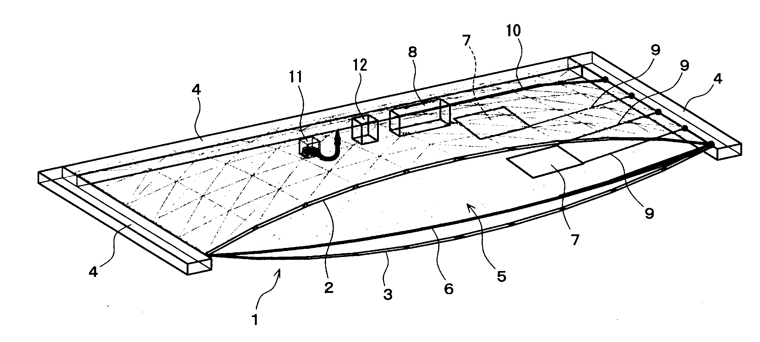
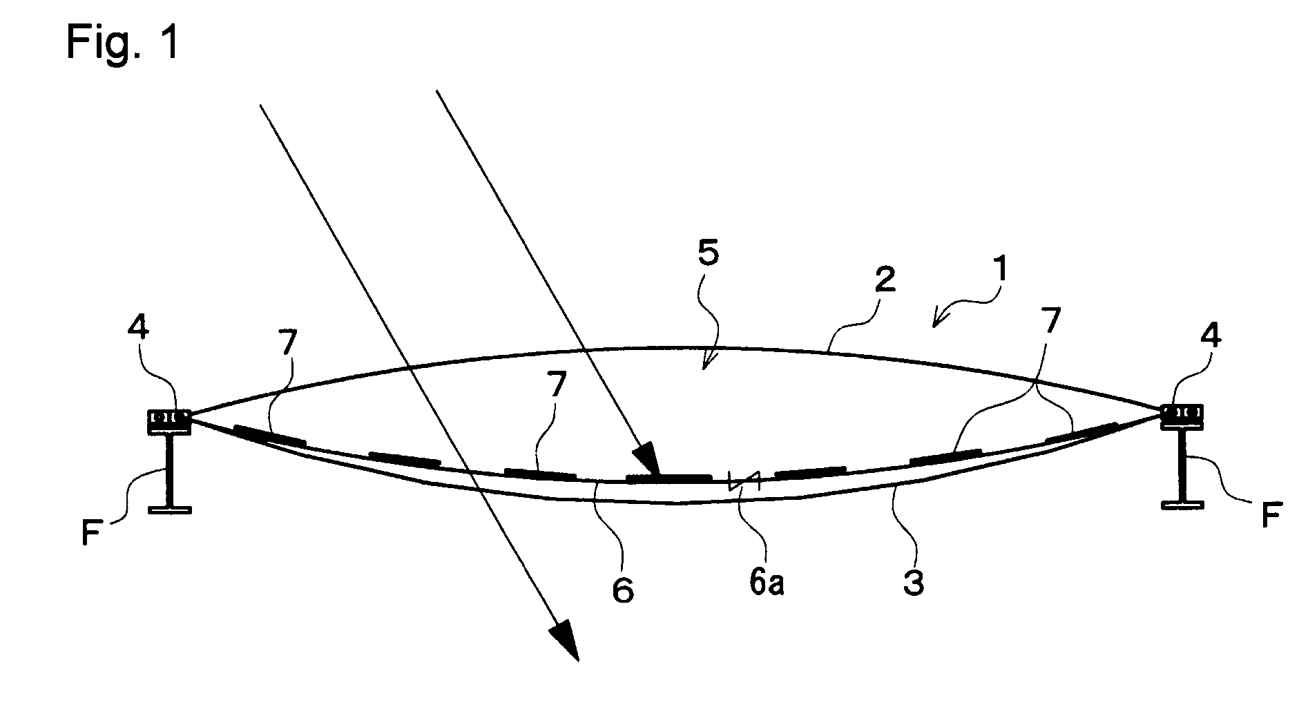
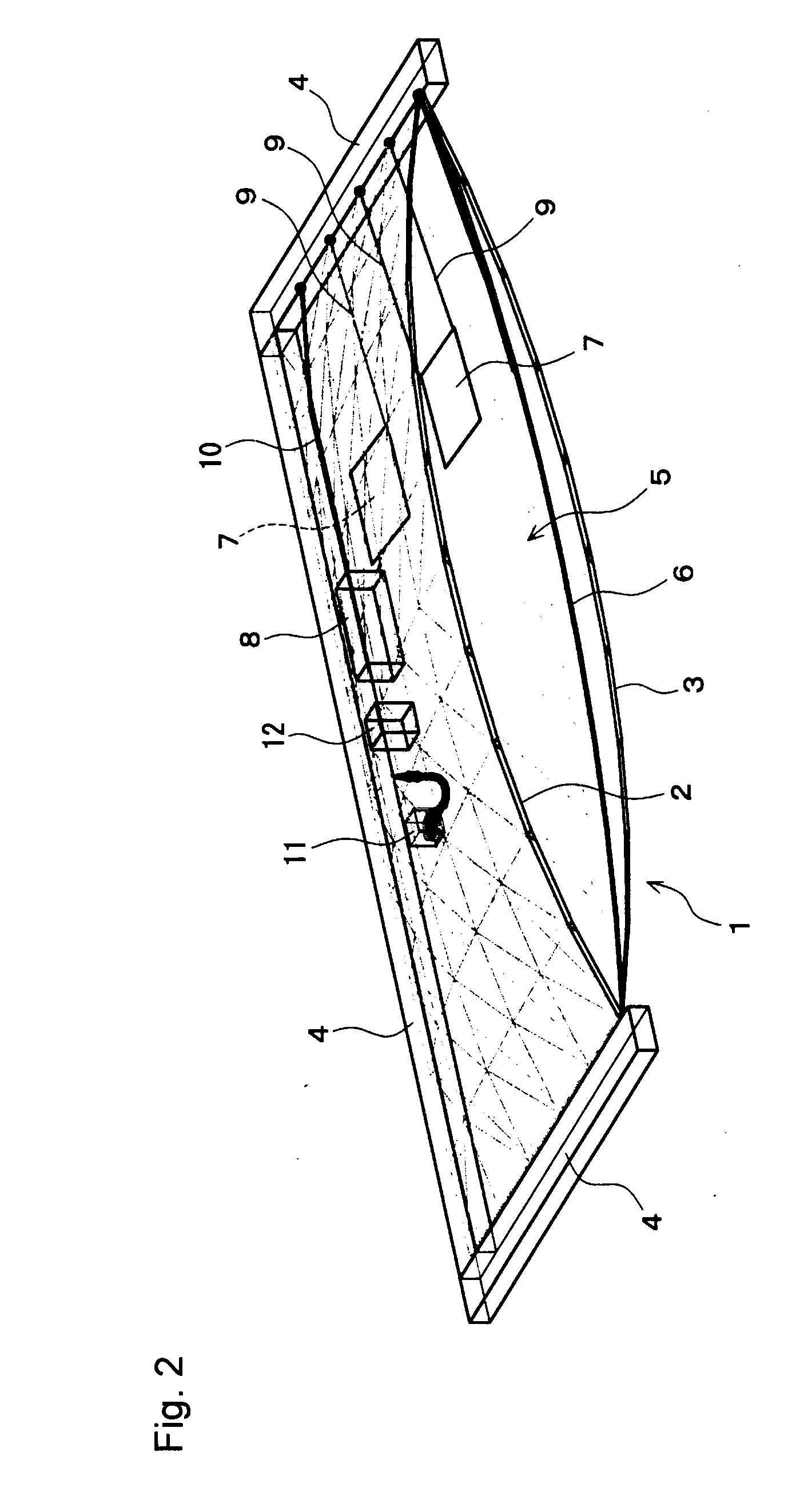
[0048]FIGS. 1 to 3 illustrate one embodiment wherein the enclosure structure for a building of the present invention is applied to a roof structure of a building, and FIG. 4 illustrates its modification.

[0049]In these Figs., the roof structure of a building C is schematically constituted by providing a plurality of solar battery modules 7 inside a pneumatic panel 1.

[0050]That is, the pneumatic panel 1 comprises an outer film material 2 and an inner film material 3 formed in two rectangle sheets, each made of a transparent plastic film material such as an ethylene / tetrafluoroethylene copolymer (hereinafter referred to as ETFE), air-tightly integrated along the respective peripheries, and held by a peripheral frame 4. As a result, an inner space 5 is created between the outer film material 2 and the inner film material 3. Further, the roof of the building C is constituted by a plurality of such pneumatic panels 1 supported by the peripheral frame 4 in such a manner that the respective...


PUM


Abstract

To provide an enclosure structure for a building, which can maintain a high power generation efficiency without formation of irregularities on the surface of the enclosure such as a roof, nor application of an external force to solar battery modules, and which can form a lightweight enclosure capable of photovoltaic generation.
An enclosure structure for a building, comprising an outer film material made of a light transmitting material and arranged on the outer surface side of the building, an inner film material arranged along inside of the outer film material, an intermediate film material disposed between the outer film material and the inner film material, an air supply means for supplying air to the space between the outer film material and the inner film material, and solar battery modules 7 provided on the inner surface of the intermediate film material.

Description

TECHNICAL FIELD[0001]The present invention relates to an enclosure structure for various buildings such as an atrium and a greenhouse, which has a double film structure and has a power generation function by the sunlight.BACKGROUND ART[0002]In recent years, from demands for environmental protection and energy saving, a technique of installing solar battery modules on a roof which is one type of an enclosure for a building and converting the sunlight energy which is natural energy to electric power to use it as a power resource for inside of the building and also to sell remained power, is in practical use.[0003]On the other hand, as the roof structure, a structure composing the roof by disposing a film material is known.[0004]Since in such a roof structure using a film material, the film surface has a curved shape with a specific tension applied, there is a problem of the difficulty to attach the above mentioned solar battery modules.[0005]Therefore, the following Patent Document 1 ...

Claims


Application Information

Patent Timeline
IPC IPC(8): E06B7/02H01L31/042
CPCE04H15/20E04H2015/203Y02B10/12Y02E10/50Y02E10/47A01G9/1415A01G9/243H02S20/00Y02B10/20F24J2/5271H02S20/20F24S20/80Y02A40/25Y02P60/12Y02B10/10
Inventor NISHIKAWA, KAORUNAKAO, TAKUYA
Owner ASAHI GLASS CO LTD
Why Eureka
Try Eureka