Method for Processing Industrial and Domestic Wastes

a technology for industrial and domestic waste, applied in the field of chemical technology and equipment, can solve the problems of reducing the volume of gas, affecting the use of obtained gas in power generation cycle and for synthesis of, e.g., petrol, and reducing the thermal power of obtained gas and its chemical composition, so as to improve the discharge conditions of slag, increase the cost-effectiveness, and increase the quality and quantity

Inactive Publication Date: 2010-10-07
STRYZHAK SERGIY YURIYOVYCH +1
View PDF8 Cites 2 Cited by
  • Summary
  • Abstract
  • Description
  • Claims
  • Application Information

AI Technical Summary

Benefits of technology

[0007]An object of the invention is to increase the cost-effectiveness by acceleration of processing, to increase quality and quantity of gas obtained at processing for its further use and to improve slag discharge conditions. Set tasks are solved by inventive method for organic industrial and household waste processing, comprising supplying waste into the apparatus—reactor through the vertical loading channel into molten salt and/or alkali mix to area of high-temperature processing within the temperature range from 850 to 95

Problems solved by technology

However, the disadvantage of said solutions is that the volume minimization is connected with degradation of both thermal power of obtain

Method used


Image

  • Method for Processing Industrial and Domestic Wastes
  • Method for Processing Industrial and Domestic Wastes
  • Method for Processing Industrial and Domestic Wastes

Examples


Embodiment Construction

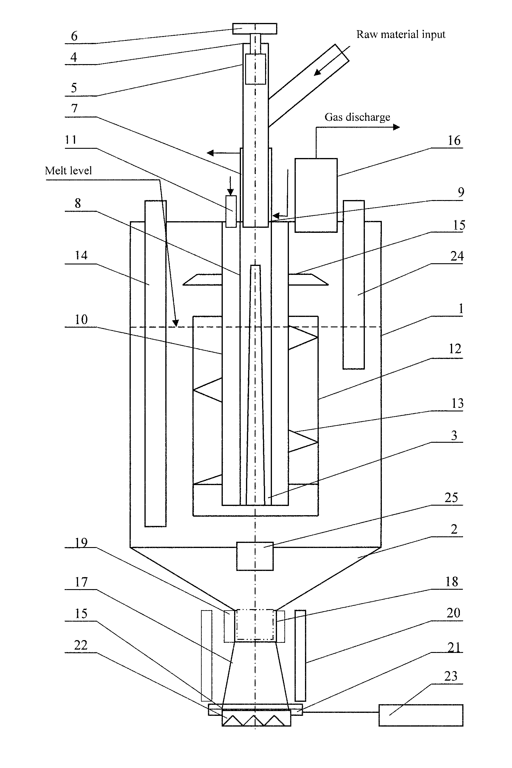
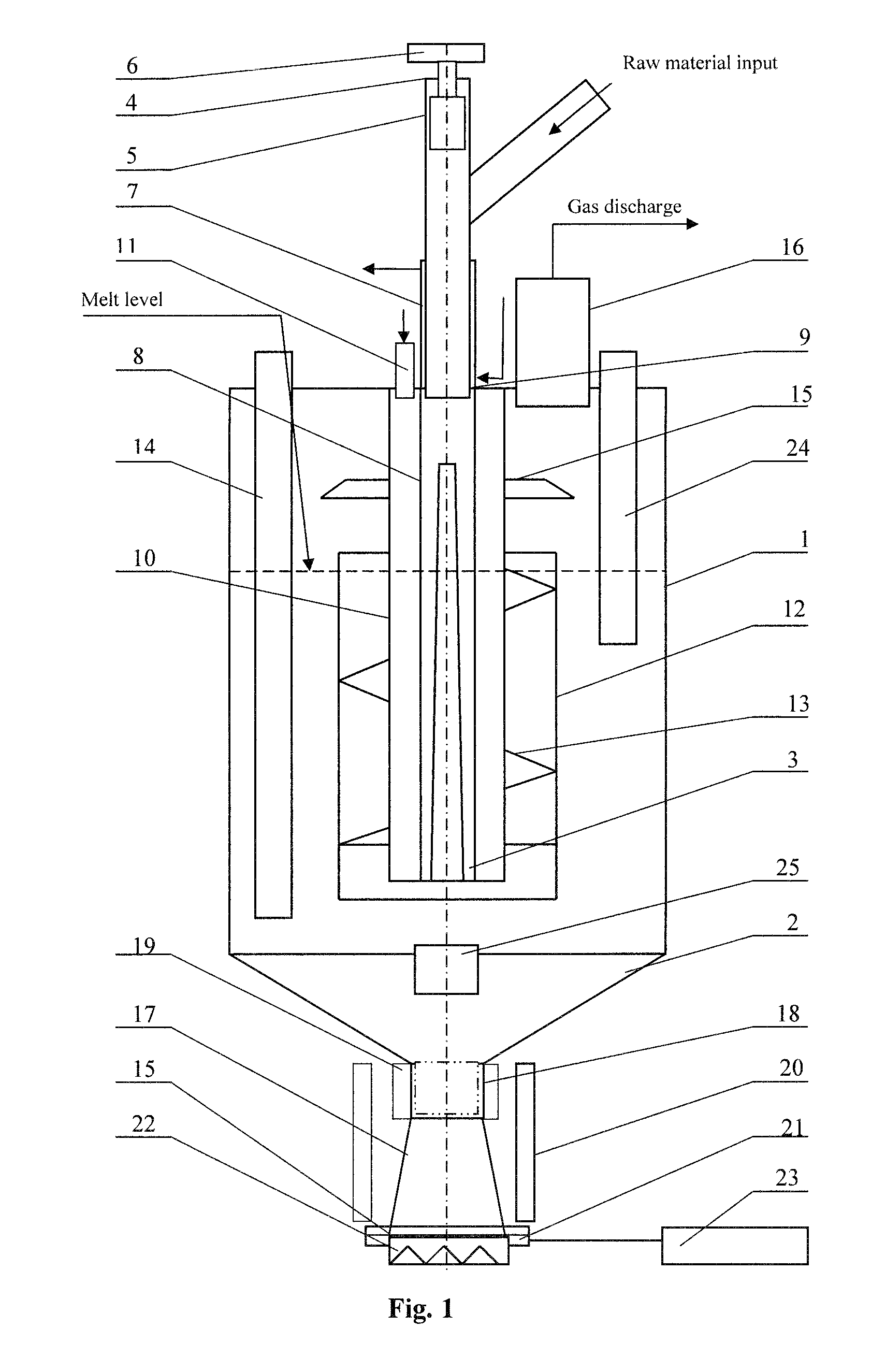
[0016]The implementation of the invention and operation of the apparatus are described below.

[0017]The reactor for industrial and household waste processing has cylindrical vessel 1 with conical bottom 2. Device for waste loading 4 is installed in direction of the vessel 1, at that the lower end of the waste loading device 4 is located under reactor's cover. Vertical loading channel 3 of the waste loading device 4 is equipped with the piston 5 with the drive 6 of reciprocal motion and cooler 7. The lower open outlet end of the loading device pipe 4 is located at level of the lower end of the cooler 7. The pipe of the loading device 4 has an opening for waste supply into the loading device pipe 4 under the upper position of the piston 5. The loading device pipe 4 is turned into the reactor pipe 8 in such a way that the upper annular clearance between the pipe of the loading device 4 and reactor pipe 8 is blocked with the bridge 9.

[0018]Damper chamber 10 is located coaxially with reac...


PUM


Abstract

The invention relates to chemical technology and equipment, in particular, to methods and apparatuses for pyrolysis (gasification) in molten salts and/or alkalis of organic household and industrial waste. The task of the invention is to increase quality and quantity of obtainable pyrolysis gas.
Set task is achieved by formation of gas-tight plug from compressed waste in the supply channel. From outside of loading channel a layer of products of low-temperature waste processing is formed, at that along the loading channel temperature regime in the range from 20 to 550° C. is formed. Temperature regulation in the loading channel is carried out by dosed supply of water vapor and/or carbon dioxide into product layer of low-temperature processing waste.
Metals, oxides, salts or oxide hydrates thereof are added to waste as processing catalysts. Water vapor and/or carbon dioxide are supplied into the area of high-temperature processing.
Silicon dioxide is added to waste for melt regeneration.
The pipe of the waste loading device in the apparatus is equipped with the cooler for method implementation. The reactor pipe, damper chamber and shell of operating area are located coaxially with the pipe of loading device in the apparatus. The blades, providing melt twisting and dispersion of gaseous products in melts, are installed in the operating area of the device. The heating tubes are located in the area between the operating area shell and vessel. The apparatus is equipped with the displacing device for slug discharge.
Proposed method and device allow to obtain optimal gas composition for its further use in production of electric power of for synthesis of, for example, alternative engine oil. At that oxygen or air are not used and harmful and atmospheric emission are practically absent.

Description

CROSS-REFERENCE TO RELATED APPLICATION[0001]This application is a continuation of International Application PCT / UA2008 / 000053, filed Aug. 29, 2008, the disclosure of which is incorporated herein by reference.FIELD OF THE INVENTION[0002]The invention relates to chemical technology and equipment, in particular, to methods and apparatuses for processing (pyrolysis and gasification) in volume in molten salts and / or alkalis of household and industrial waste containing organic substances.BACKGROUND OF THE INVENTION[0003]U.S. Pat. No. 6,799,595 IPC F16K 13 / 00, F16K 13 / 10 describes the method for waste processing, which comprises waste supply into molten salts or alkalis and the apparatus for implementation thereof, wherein the waste is fed into the melt in air stream. At that flameless oxidation of waste occurs.[0004]The closest technical solution for inventive method is the method for industrial and household waste processing, comprising waste supply through loading channel into the melt ...

Claims


Application Information

Patent Timeline
IPC IPC(8): F23G5/00
CPCF23G5/027
Inventor STRYZHAK, SERGIY YURIYOVYCHSHVED, ROMAN PETROVYCH
Owner STRYZHAK SERGIY YURIYOVYCH
Why Eureka
Try Eureka