Oscillator circuit

a technology of oscillator circuit and oscillator, which is applied in the direction of pulse manipulation, pulse technique, instruments, etc., can solve the problems of adverse effects on the circuit operation, and achieve the effect of gradually changing the set voltag

Active Publication Date: 2010-10-07
ROHM CO LTD
View PDF2 Cites 17 Cited by
  • Summary
  • Abstract
  • Description
  • Claims
  • Application Information

AI Technical Summary

Benefits of technology

[0023]With such an embodiment, the set voltage can be gradually changed. Thus, the output voltage of the switching regulator can be gradually switched (in a soft-start manner) without the need to generate an additional soft-start voltage. That is to say, such an arrangement does not require a capacitor used to generate such a soft-start voltage.

Problems solved by technology

With an arrangement in which a pulse signal is generated by slicing the cyclic signal at a predetermined level, in a case in which the peak voltage of the cyclic signal (sloping waveform) changes, the duty ratio of the pulse signal fluctuates, leading to adverse effects on the circuit operation, which is a problem.

Method used


Image

  • Oscillator circuit
  • Oscillator circuit
  • Oscillator circuit

Examples


first embodiment

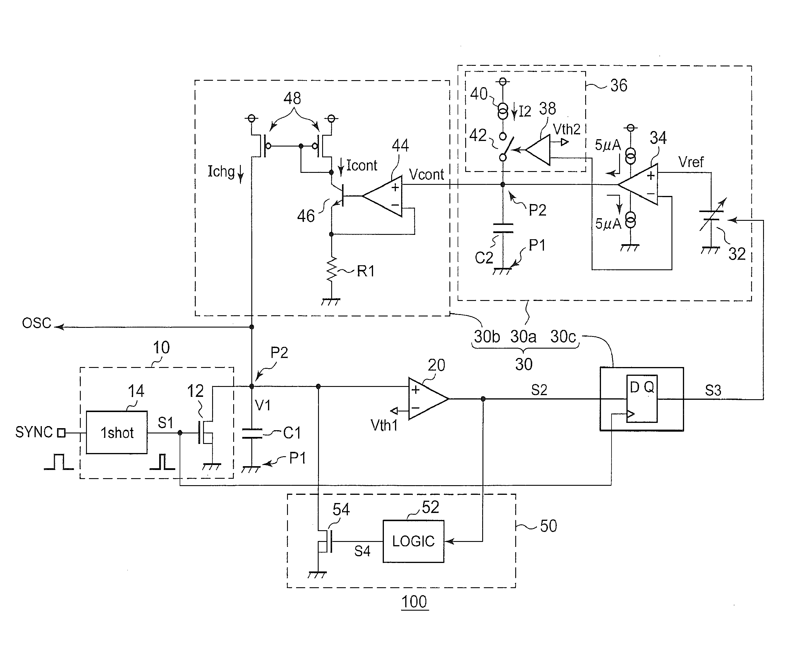
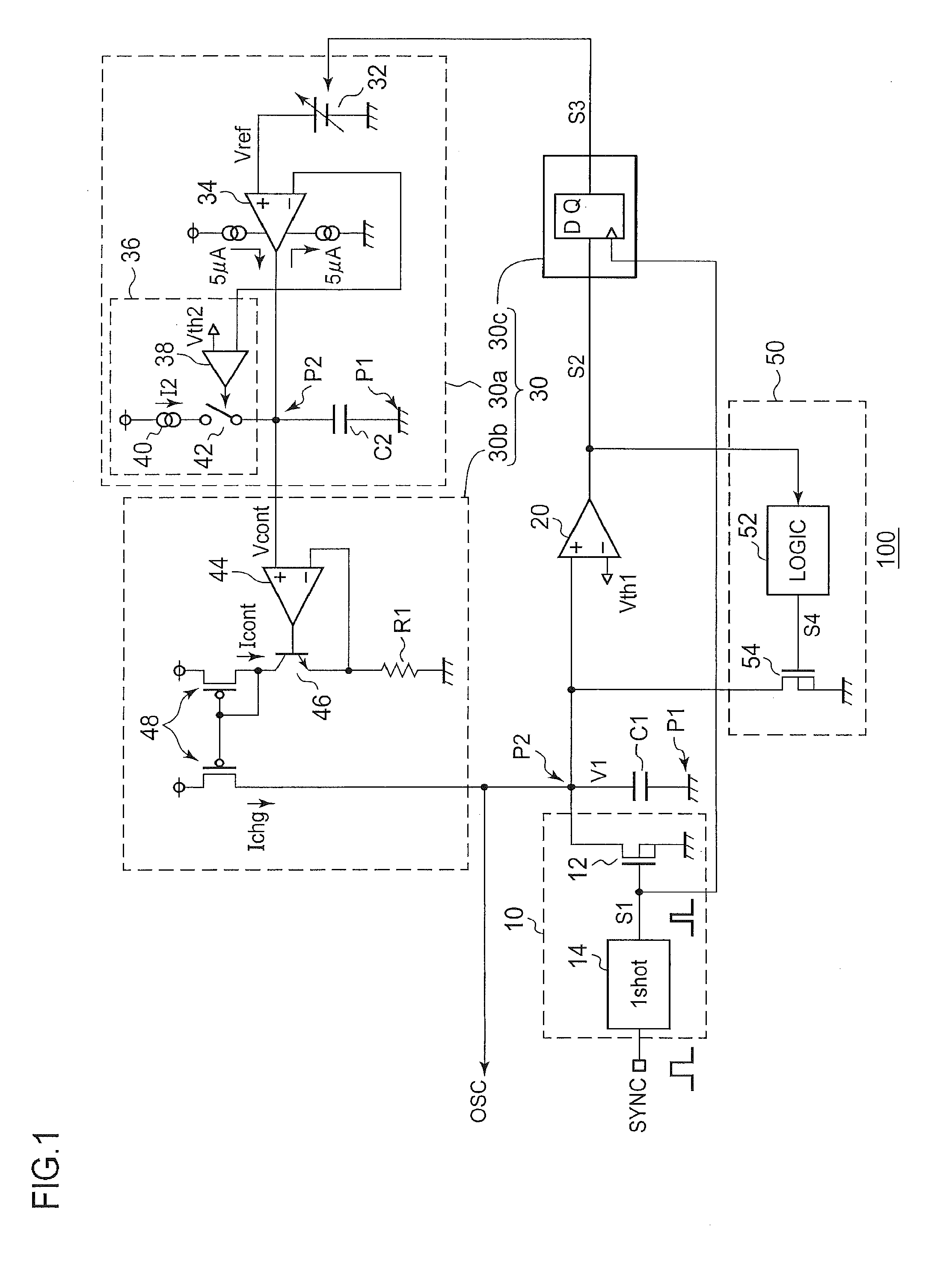
[0036]An oscillator circuit 100 according to a first embodiment is configured to enable the mode to be switched between an external synchronization mode and a self-running mode. In the external synchronization mode, the oscillator circuit 100 generates a cyclic signal OSC having a sloping waveform, synchronously with a synchronization signal SYNC received from an external circuit. In the self-running mode, the oscillator circuit 100 oscillates independent of the synchronization signal SYS, thereby generating a cyclic signal OSC.

[0037]FIG. 1 is a circuit diagram which shows a configuration of the oscillator circuit 100 according to the first embodiment. The oscillator circuit 100 includes a first discharging circuit 10, a first capacitor C1, a first comparator 20, a charging circuit 30, and a second discharging circuit 50.

[0038]The first capacitor C1 is arranged such that a first terminal P1 is grounded, i.e., the electric potential at the first terminal P1 is fixed. The first discha...

second embodiment

[0082]Description will be made in the second embodiment regarding a soft-start technique which enables the switching regulator 200 to gradually change the output voltage Vout. FIG. 4 is a circuit diagram which shows a configuration of a switching regulator 200a according to the second embodiment.

[0083]The switching regulator 200a includes a control circuit 210a and an output circuit 220. The control circuit 210a includes an error amplifier 70, a PWM comparator 72, a driver 74, a switching element 76, an oscillator circuit 100, and a setting voltage generating unit 80.

[0084]Description has been made above regarding the error amplifier 70, the PWM comparator 72, the driver 74, and the switching element 76. The oscillator circuit 100 may have the same configuration as shown in FIG. 1. Also, the oscillator circuit 100 may have a different configuration.

[0085]The setting voltage generating unit 80 generates a setting voltage (soft-start voltage) Vs which is used as a reference voltage to...

third embodiment

[0093]FIG. 6 is a circuit diagram which shows a configuration of a system power supply according to a third embodiment. The system power supply 300 includes: a single-channel switching regulator (DC / DC converter) configured to generate an output voltage Vout; and a single-channel linear regulator (low dropout voltage regulator) configured to generate an output voltage VOUTLDO.

[0094]The system power supply 300 is configured so as to enable the voltage level to be switched between the levels of these two output voltages Vout and VOUTTLDO according to the value of the select signal SEL.

[0095]The two output voltages and the soft-start voltage SS are set to the following values according to the voltage at the SEL terminal, i.e., the high level H (2.0 V

[0096](1) SEL=L

[0097]Vout=12.3 V

[0098]VOUTLDO=11.8 V

[0099]Vss=0.8 V

[0100](2) SEL=H

[0101]V...


PUM


Abstract

A first capacitor is arranged such that the electric potential at a first terminal is fixed. A first discharging circuit discharges the first capacitor at a timing that corresponds to a cyclic synchronization signal received from an external circuit. A first comparator compares the voltage at a second terminal of the first capacitor with a predetermined threshold voltage, and generate a judgment signal that corresponds to the comparison result. A charging circuit generates a charging current the current value of which is adjusted according to the level of the judgment signal at a timing that corresponds to the synchronization signal, and supplies the charging current thus generated to the first capacitor.

Description

BACKGROUND OF THE INVENTION[0001]1. Field of the Invention[0002]The present invention relates to a technique for generating a cyclic signal having a sloping waveform.[0003]2. Description of the Related Art[0004]Switching power supply devices such as a switching regulator or the like employ a pulse signal in order to switch a switching element ON and OFF. As a method for generating such a pulse signal, a technique is employed in which the charging operation and the discharging operation of a capacitor are repeatedly alternated so as to generate a cyclic signal (triangle wave signal) having a sloping waveform, and the cyclic signal thus generated is sliced at a predetermined level so as to generate a pulse signal based upon the points of intersection of the cyclic signal and the predetermined level (Patent documents 1 and 2).[0005]As an oscillator circuit configured to generate a triangle wave signal, a self-running method (self-excitation method) and an external synchronization metho...

Claims


Application Information

Patent Timeline
Patent Type & Authority Applications(United States)
IPC IPC(8): G05F1/10H03B5/08
CPCH02M1/08H03B5/26H02M3/156
Inventor NAKADA, KENJIUMEKI, NOBUAKI
Owner ROHM CO LTD
Why Eureka
Try Eureka