System and Method for Suppressing Close Clutter in a Radar System

a radar system and close clutter technology, applied in the field of electromagnetic wave processing, can solve the problems of loss of targets, missed or other undesirable effects of targets, and clutter that can vary, and achieve the effect of reducing or eliminating at least some of the disadvantages and problems

Active Publication Date: 2010-10-07
RAYTHEON CO
View PDF14 Cites 24 Cited by
  • Summary
  • Abstract
  • Description
  • Claims
  • Application Information

AI Technical Summary

Benefits of technology

[0003]The present invention provides a method and system for transmitting, receiving, and processing electromagnetic waves that substantially eliminates or reduces at least some of the disadvantages and problems associated with previous methods and systems for processing electromagnetic waves.
[0006]Important technical advantages of certain aspects of the present invention include increasing the probability that targets will be detected. By operating in the time domain to reduce or eliminate environmental interference and clutter, the system facilitates the detection of targets which may have otherwise been obscured. Other technical advantages of certain aspects of the present invention include the ability to reduce or eliminate environmental interference or clutter under a wide array of conditions and configurations. By providing a flexible method of modifying a threshold signal, the system substantially reduces or eliminates clutter associated with transmission from a moving, ground-based vehicle. Moreover, certain aspects of the present invention may represent elements of a multi-static radar system, allowing for dynamic arrangement of transmitters and receivers. That is, the location of transmitters and receivers as positioned on a vehicle, or as fixed in the ground, may be dynamically configurable according to the particular needs of a user, the terrain in which targets are located, or any other considerations. Additionally, certain aspects of the present invention may be rapidly installed or removed, allowing for quick reaction to changing events. Dynamic arrangement thus allows for optimal target detection in a variety of situations and environments. Thus, certain aspects of the present invention allow for the detection of targets when operating on a moving vehicle or in rough or difficult terrain. In addition, other technical advantages of certain aspects of the present invention include allowing a user to more precisely and accurately locate a target by utilizing multiple receivers and generating a three-dimensional image representing a target. Additionally, at appropriate times during operation, an embodiment of the present invention may allow for the background environment to be re-characterized when no targets are present. Thus, an embodiment of the present invention may be periodically re-calibrated while continuing detection of targets.

Problems solved by technology

When using impulsive radar on a moving ground vehicle, close clutter due to the environment often obscures targets a user is trying to detect.
This clutter can vary due to slight changes in the surface, vibration of the vehicle, and source and digitizer jitter.
Correcting for clutter by simply decreasing the sensitivity with which targets are detected, may result in some targets being missed or other undesirable effects.
As a result, previous attempts to solve this problem have resulted in lost targets, lowering the probability of detection, and not accounting for variations in the clutter.

Method used


Image

  • System and Method for Suppressing Close Clutter in a Radar System
  • System and Method for Suppressing Close Clutter in a Radar System
  • System and Method for Suppressing Close Clutter in a Radar System

Examples


Embodiment Construction

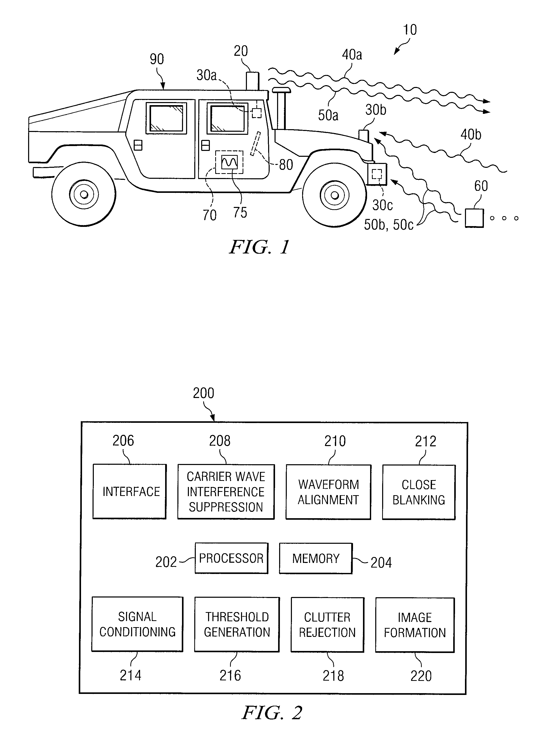
[0013]FIG. 1 illustrates a particular embodiment of a system 10 for processing electromagnetic waves transmitted by a transmitter 20 and received by a receiver 30. System 10 includes transmitter 20, receiver 30, a system controller 70, a display 80, and a vehicle 90. To facilitate the detection of a target 60, system 10 processes electromagnetic waves reflected from target 60 and other sources, removes electromagnetic interference and clutter, and displays an image representing target 60 on display 80.

[0014]Transmitter 20 transmits calibration waves 40 and operating waves 50 generated by system controller 70. In particular embodiments transmitter 20 may include a power source, oscillator, an amplifier, and antenna. In general, however, transmitter 20 may be any appropriate combination of hardware and / or software suitable for transmitting calibration waves 40 and operating waves 50 in system 10. Transmitter 20 may be mounted on vehicle 90. Additionally, transmitter 20 may be mounted ...


PUM


Abstract

A system for processing electromagnetic waves in a radar system is disclosed. The system includes a transmitter operable to transmit operating waves and calibration waves, one or more receivers operable to receive reflected calibration waves and operating waves, and a system controller operable to process the received calibration waves and operating waves. The system controller may process the received waves by generating a threshold signal based on the calibration waves, and comparing the threshold signal to the operating waves. The system controller may also process operating waves and calibration waves in accordance with one or more signal conditioning algorithms. Additionally, the system controller may display an image representing a target on a display by comparing received operating waves with the generated threshold signal.

Description

TECHNICAL FIELD OF THE INVENTION[0001]This invention relates generally to processing electromagnetic waves, and more particularly to a method and system processing electromagnetic waves to reduce or eliminate clutter in a radar system.BACKGROUND OF THE INVENTION[0002]When using impulsive radar on a moving ground vehicle, close clutter due to the environment often obscures targets a user is trying to detect. This clutter can vary due to slight changes in the surface, vibration of the vehicle, and source and digitizer jitter. Correcting for clutter by simply decreasing the sensitivity with which targets are detected, may result in some targets being missed or other undesirable effects. As a result, previous attempts to solve this problem have resulted in lost targets, lowering the probability of detection, and not accounting for variations in the clutter.SUMMARY OF THE INVENTION[0003]The present invention provides a method and system for transmitting, receiving, and processing electro...

Claims


Application Information

Patent Timeline
Patent Type & Authority Applications(United States)
IPC IPC(8): G01S13/02
CPCG01S7/40G01S7/414G01S2013/9389G01S2013/9375G01S2013/9382G01S13/931G01S2013/93273G01S2013/93275G01S2013/93271
Inventor HOLZHEIMER, TIMOTHY R.GOODMAN, VERNON R.
Owner RAYTHEON CO
Why Eureka
Try Eureka