Digital holography device and phase plate array

Inactive Publication Date: 2010-10-07
NAT UNIV KYOTO INST OF TECH
View PDF4 Cites 27 Cited by
  • Summary
  • Abstract
  • Description
  • Claims
  • Application Information

AI Technical Summary

Benefits of technology

[0070]As described above, a digital holography device according to the present invention includes the phase-shifting element that splits the light emitted from the light source into two kinds of reference light beams having different phases in a plane perpendicular to a direction in which the light emitted from the light source travels. This yields the effect of realizing a better quality of a reconstructed image of the subject than that of a reconstructed image obtained by a digital holography device in the conventional arrangement and the effect of making the phase-shifting element easier to manufacture than a phase-shifting element for the conventional digital holography device.
[0071]As described above, another digital holography device according to the present invention includes a differential optical path generating element that generates the first optical-path object light beams and second optical-path object light beams, which are different in differential optical path from each other, according to the object light beams, and generates the first optical-path reference light beams and second optical-path reference light beams, which are different in differential optical path from each other, according to the light beams emitted from the light source. With this arrangement, it is possible to concurrently obtain first and second interfer

Problems solved by technology

Also, the arrangement shown in FIG. 23 requires an imaging optical system, resulting in the problem caused by aberration.
In addition, diffraction occurs due to a phase-shifting array device.
This requires the setting of the optical system in micro

Method used


Image

  • Digital holography device and phase plate array
  • Digital holography device and phase plate array
  • Digital holography device and phase plate array

Examples


first embodiment

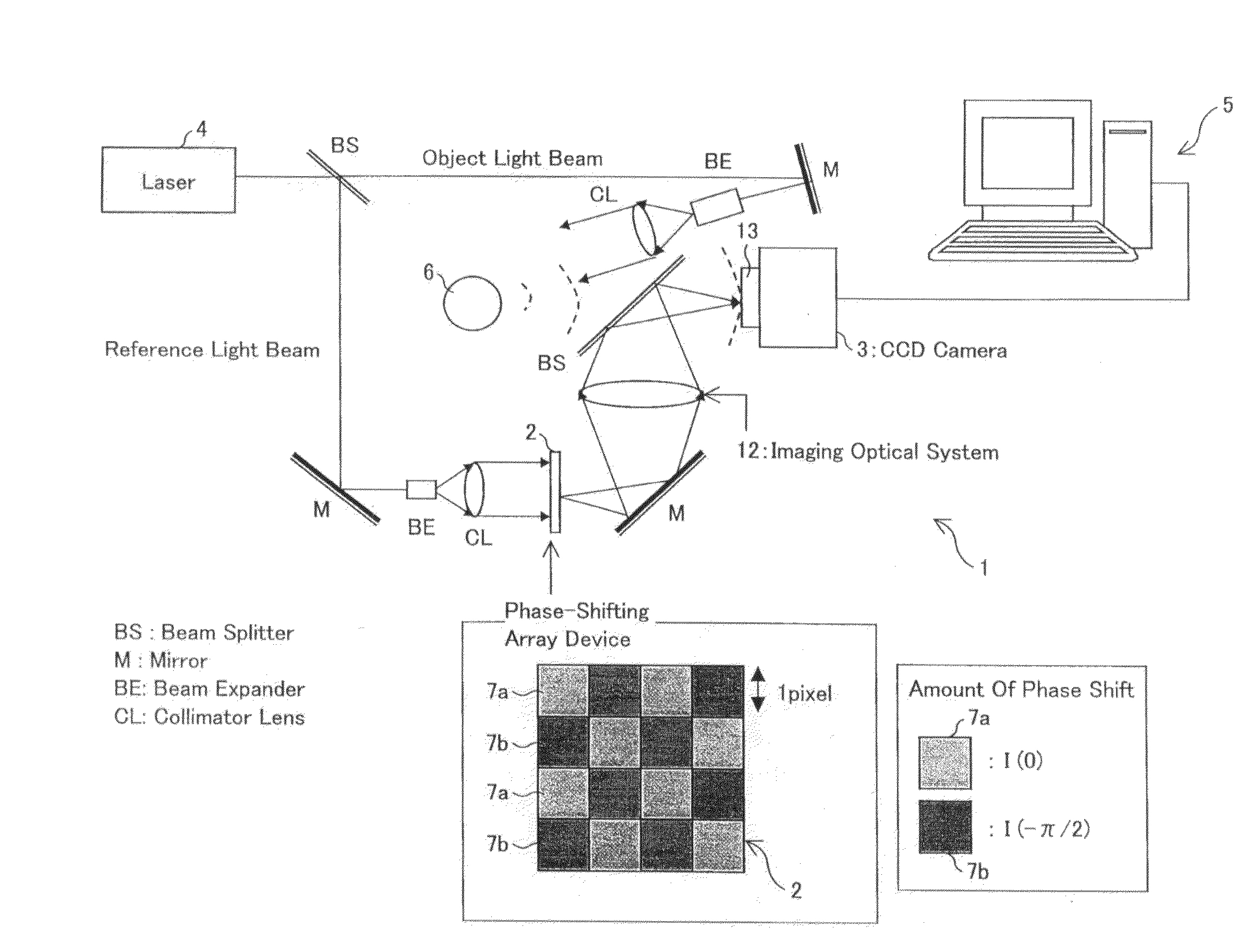
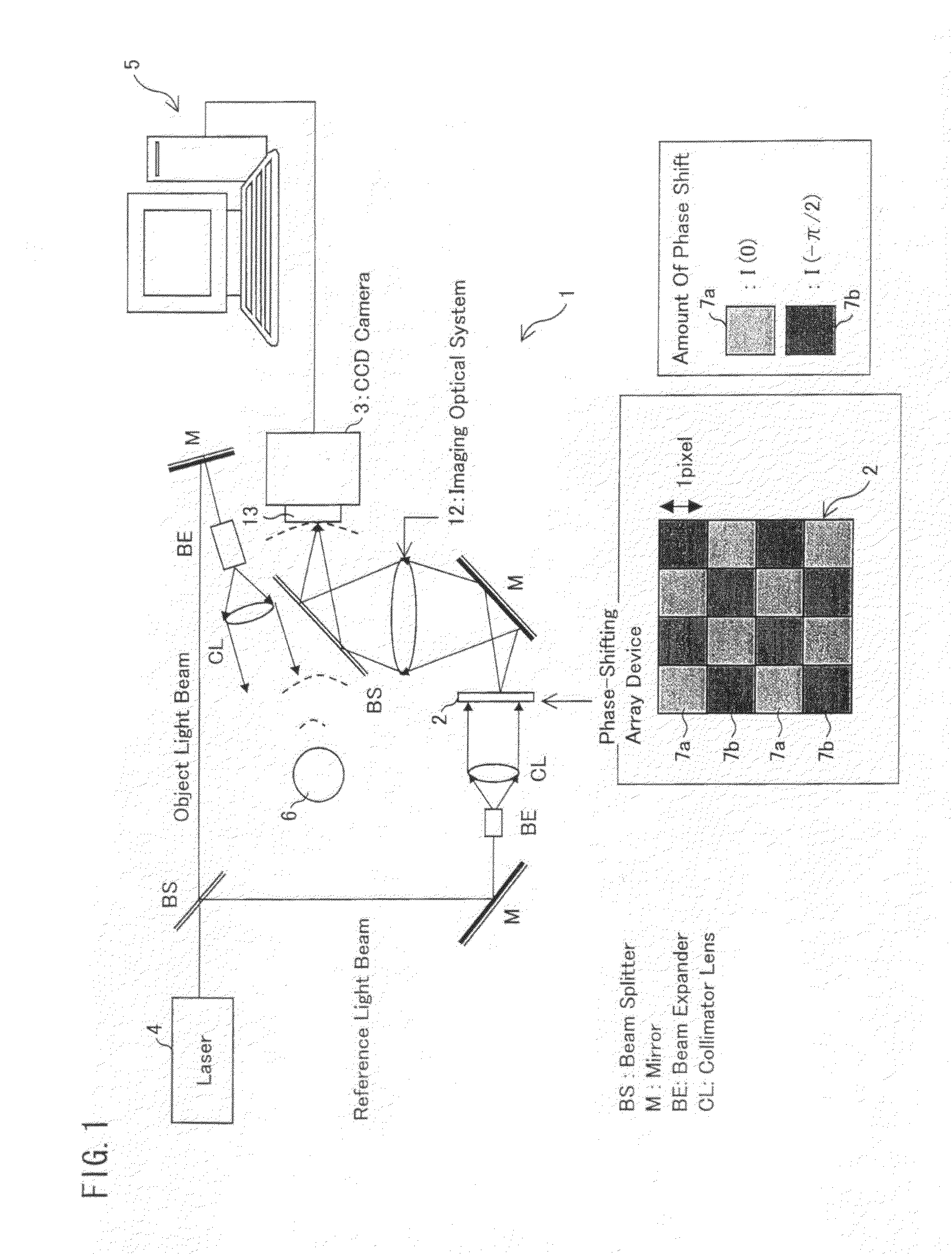
[0129]FIG. 1 is an explanatory diagram schematically showing the configuration of a digital holography device 1 according to First Embodiment. The digital holography device 1 includes a light source 4 that emits laser light. The laser light emitted from the light source 4 is split into two light beams by a beam splitter BS. One of the separate light beams is reflected from a mirror M, passes through a beam expander BE, and then collimated by a collimator lens CL to turn into collimated light beams. The collimated light beams illuminate a subject 6 and are scattered from the subject 6 to turn into object light beams. The object light beams pass through another beam splitter BS and enter an image-capturing plane 13 of the CCD camera 3.

[0130]Meanwhile, the other of the separate light beams into which the laser light has been split by the beam splitter BS is reflected from another mirror M. The reflected light beam passes through another beam expander BE and is collimated by another col...

second embodiment

[0166]FIG. 6 is an explanatory diagram schematically showing the configuration of a digital holography device 1c according to Second Embodiment. Components that are the same as those described in First Embodiment are given the same reference numerals, and detailed explanations thereof are omitted here.

[0167]The digital holography device 1c includes a light source 4 that emits laser light. The laser light emitted from the light source 4 is split into light beams by a first beam splitter BS. One of the separate light beams is reflected from a first mirror M, passes through a first beam expander BE, and then collimated by a first collimator lens CL to turn into a collimated light beam. The collimated light beam illuminates a subject 6 and is scattered from the subject 6 to turn into an object light beam. The object light beam passes through a second beam splitter BS and enters an array device 14.

[0168]Meanwhile, the other of the separate light beams, into which the laser light has been...

third embodiment

[0184]FIG. 11 is an explanatory diagram schematically showing the configuration of a digital holography device 1d according to Third Embodiment. Components that are the same as those described in the foregoing embodiments are given the same reference numerals, and detailed explanations thereof are omitted here.

[0185]The digital holography device 1d includes a light source 28a that emits beams of green laser light with a wavelength corresponding to green and a light source 28b that emits beams of red laser light with a wavelength corresponding to red. The green laser light beam emitted from the light source 28a is reflected from a first mirror M. The reflected green laser light beams pass through a first half-mirror HM, and then enter a second half mirror HM. The red laser light beams emitted from the light source 28b are reflected from the first half mirror HM and then enter the second half mirror HM.

[0186]The green laser light beams and red laser light beams reflected from the seco...


PUM


Abstract

Provided is a digital holography device having a simple configuration and an improved image quality, including: a light source that emits light, the light source being provided for supply of object light beams formed by radiation, transmission, scattering, reflection, or diffraction of the emitted light from a subject; an array device that splits the light emitted from the light source into two kinds of reference light beams having different phases in a plane perpendicular to a direction in which the light emitted from the light source travels; a CCD camera having an image-capturing plane on which two kinds of interference fringe patterns are recorded, the interference fringe patterns being formed by interferences between the two kinds of reference light beams, which have been produced by the array device, and the object light beams, which have been formed by radiation, transmission, scattering, reflection, or diffraction from the subject; and an image reconstruction device that generates a reconstructed image of the subject from the two kinds of interference fringe patterns recorded on the image-capturing plane.

Description

TECHNICAL FIELD[0001]The present invention relates to: a digital holography device that generates a reconstructed image of a subject according to interference fringes formed by interferences between object light beams and reference light beams; and a phase plate array used in the digital holography device.BACKGROUND ART[0002]Hereinafter, phases and angles are expressed in radians. The inventors of the present application have suggested a digital holography device including a phase-shifting array element that splits incoming light into four kinds of reference light beams with mutually different phases and emits the reference light beams (Patent Literature 1). FIG. 23 is an explanatory diagram showing the configuration of a conventional digital holography device 101. The digital holography device 101 includes a light source 104 that emits laser light. The laser light emitted from the light source 104 is split into laser light beams by a beam splitter BS. One of the separate laser ligh...

Claims


Application Information

Patent Timeline
IPC IPC(8): G03H1/04G02B27/28
CPCG03H1/0443G03H1/041G03H1/12G03H2001/0447G03H2001/0458G03H2001/0469G03H2001/0471G03H2001/0875G03H2001/303G03H2222/34G03H2222/42G03H2222/45G03H2223/13G03H2223/15G03H2223/19G03H2225/35G03H1/0866G03H2001/0452
Inventor AWATSUJI, YASUHIROKANEKO, ATSUSHIKOYAMA, TAKAMASATAHARA, TATSUKIWAKAMATSU, TAKESHI
Owner NAT UNIV KYOTO INST OF TECH
Why Eureka
Try Eureka