Method for the uninterrupted operation of a gas liquefaction system

a gas liquefaction and continuous operation technology, applied in the direction of solidification, non-positive displacement fluid engines, lighting and heating apparatus, etc., can solve the problems of difficult startup or restart of single-shaft gas turbines, failure of the lng production process, and production downtime, so as to reduce the emission of greenhouse gases, reduce the load of compressors, and increase the thermal efficiency of plants

Inactive Publication Date: 2010-10-14
SIEMENS AG
View PDF3 Cites 37 Cited by
  • Summary
  • Abstract
  • Description
  • Claims
  • Application Information

AI Technical Summary

Benefits of technology

[0021]When variable-speed (converter-fed) electric motors are used and are supplied with power from a modern gas and steam (combined cycle) power plant, the thermal efficiency of the plant increases and the emission of greenhouse gases is reduced.
[0022]By a suitable layout of the drive facilities, the refrigerant compressors can be started up again, after a process-induced shutdown, within 10 to 30 minutes instead of the 8 to 12 hours for standby turbines or fixed speed electric motors with start-up converters, without reducing the compressor load and without burning off refrigerant.
[0023]With an appropriate layout of the supplying stand-alone power plant, and integration of the automation systems involved (e.g. power plant, converter drives, compressors), production from the eLNG plant can also be kept interruption-free during a malfunction shutdown of a generator in the power plant.
[0024]Potential dangers to personnel are reduced by the relocation of maintenance work out of the explosion-risk process area into the power plant area.
[0025]When variable-speed electric motors with an application-specific layout are used, it is easier to effect optimization for the process conditions within the limitations on the criteria for compressor selection relating to the rotational speed and power of the gas turbines.

Problems solved by technology

Generic disadvantages of these plants are production down times during the regular maintenance work which is required on the gas turbines, difficult startup or restart of the compressors with single-shaft gas turbines, together with the direct dependence of the size and the power output of the refrigerant compressor on the type-tested gas turbines themselves, the shaft output of which depends in turn on ambient conditions which fluctuate daily or undergo seasonal changes.
However, the disadvantage of this method is that the LNG production process has then already failed, and it takes some hours until the refrigerant compressor concerned has started up again and become thermally stable.

Method used


Image

  • Method for the uninterrupted operation of a gas liquefaction system
  • Method for the uninterrupted operation of a gas liquefaction system
  • Method for the uninterrupted operation of a gas liquefaction system

Examples


Embodiment Construction

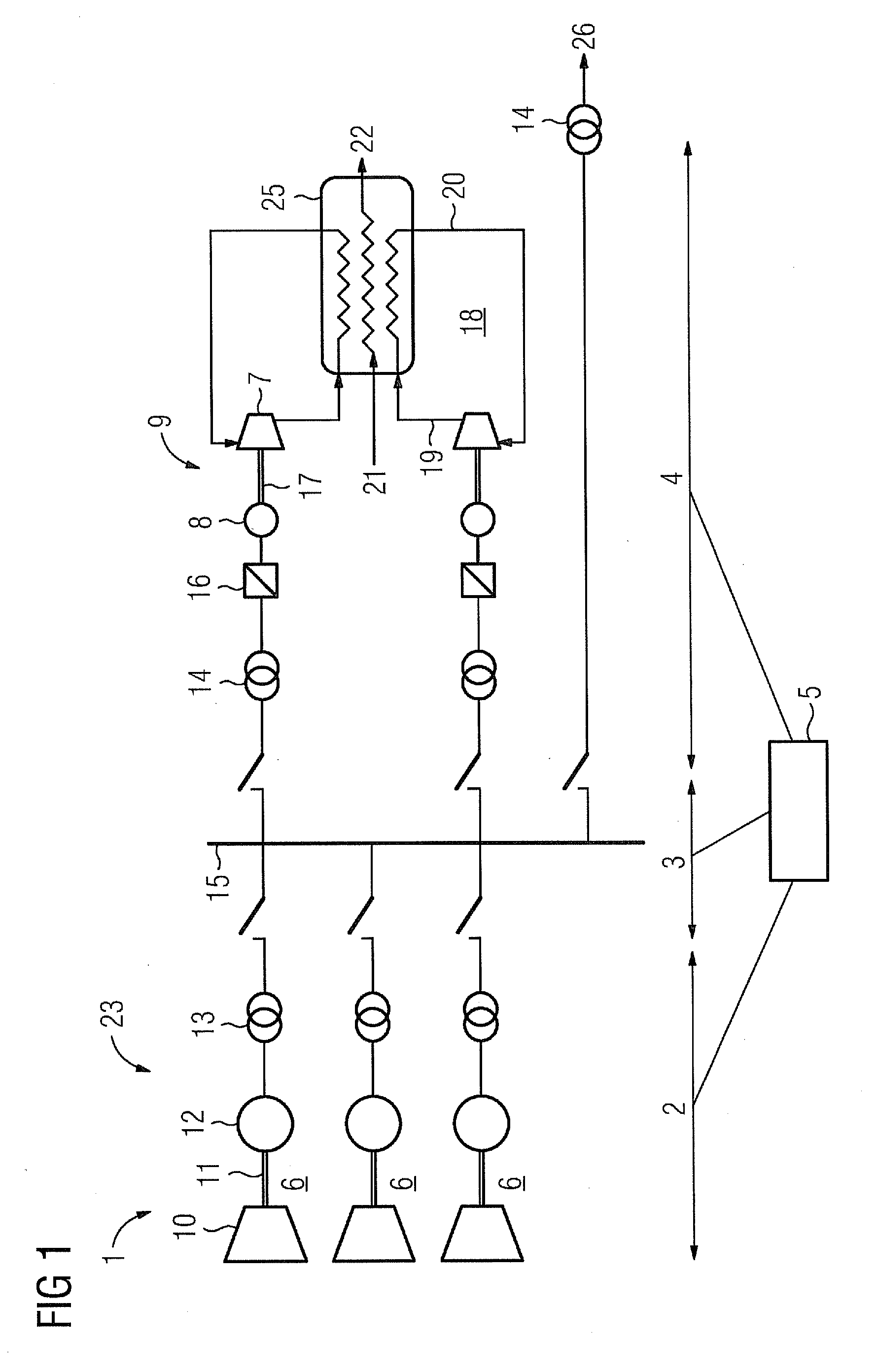
[0035]FIG. 1 shows an integrated solution for a gas liquefaction plant 1 with a stand-alone power plant 23 as the power generation module 2, a transfer module 3 for distributing the power and a refrigerant compression module 4. A control system 5 is connected to the power generation module 2, the transmission module 3 and the refrigerant compression module 4.

[0036]The power generation module 2 incorporates three turbine sets 6, each with a turbine 10 and a generator 12, which are connected via a shaft 11. However, the power generation module 2 can also incorporate less than three or more than three turbine sets 6.

[0037]The turbine sets 6 are in each case connected via an electrical transformer 13 to the power plant busbar 15 of the transmission module 3, which makes the electrical power available to the motors in the refrigerant compression module 4 and / or other consumers 26.

[0038]In the refrigerant compression module 4, the variable-speed electric motors 8 of the refrigerant compre...


PUM


Abstract

A method for the uninterrupted operation of a gas liquefaction system is provided, wherein the operation is continuously monitored for at least those users of the refrigerant compressor component which represent a two-digit percentage of the total load on the refrigerant compressor component. A total instantaneously available negative load reserve is calculated, and at least one predetermined turbine is switched off when the load reserve reachable via a frequency regulation of the one or more refrigerant compressors is lower than the energy demand of the largest of the refrigerant compressors and either a refrigerant compressor fails or a speed of frequency change for the power supply network for the gas liquefaction system exceeds a present threshold.

Description

CROSS REFERENCE TO RELATED APPLICATIONS[0001]This application is the US National Stage of International Application No. PCT / EP2008 / 058821 filed Jul. 8, 2008, and claims the benefit thereof. The International Application claims the benefits of European Patent Application No. 07013711.2 EP filed Jul. 12, 2007. All of the applications are incorporated by reference herein in their entirety.FIELD OF INVENTION[0002]The invention relates to a method for the uninterrupted operation of a gas liquefaction plant, in particular a natural gas liquefaction plant.BACKGROUND OF INVENTION[0003]The term liquefied natural gas (abbreviated to LNG) is applied to natural gas which has been liquefied by cooling it. LNG has less than 1 / 600th of the volume of natural gas at atmospheric pressure, and is thus especially suitable for transport and storage purposes; in this aggregate state it cannot be used as a fuel.[0004]In power plants which are upstream of a plant for the liquefaction of light carbohydrates...

Claims


Application Information

Patent Timeline
Patent Type & Authority Applications(United States)
IPC IPC(8): F25J1/02
CPCF04D25/04F04D25/16F25J1/0022F25J1/027F25J2280/20F25J1/0298F25J2230/22F25J2240/70F25J2240/80F25J1/0284
Inventor BALLING, REINERHEINEMANN, ANDREASKLEINER, FRITZTOMSCHI, ULRICH
Owner SIEMENS AG
Why Eureka
Try Eureka