Method and apparatus for producing battery pack

a battery pack and battery technology, applied in the direction of cell components, cell component details, food shaping, etc., can solve the problems of increased volume and weight of the pack case, increased cost, and increased risk of abnormal conditions, so as to improve productivity, reduce cross-sectional shape, and improve productivity

Inactive Publication Date: 2010-10-14
GK BRIDGE 1
View PDF6 Cites 16 Cited by
  • Summary
  • Abstract
  • Description
  • Claims
  • Application Information

AI Technical Summary

Benefits of technology

[0052]According to the embodiment of claim 1, a resin of polyamide adhesive or polyurethane adhesive, which is capable of being molded at low temperature and low pressure, is used as the molding material. It is therefore possible to prevent the secondary battery and the circuit board from being adversely affected by high temperature and high pressure. It is also possible to protect the heat sensitive element which is often included in the circuit board. Also, the use of the above resin requiring a short molding time permits a further improvement in productivity. In addition, a predetermined tensile stress is applied to the solidified resin strongly bonded to the interior of the runner system for a predetermined time to deform the solidified resin such that the diameter of the cross-sectional shape thereof decreases, thereby gradually separating the solidified resin from the inner surface of the runner system. Thereafter, the nozzle is moved away from the resin injection inlet to cut off the solidified resin from the nozzle. As a result, it is possible to prevent the solidified resin from breaking halfway and remaining in the runner system when the nozzle is moved away from the resin injection inlet in one stroke. This permits a significant improvement in productivity.
[0053]According to the embodiment of claim 2, the runner system is composed of a sprue connected to the resin injection inlet of a mold and a plurality of runners branching off from the sprue. In the case of separating the solidified resin formed in the sprue by the solidification of the molding material and bonded to the inner surface of the sprue therefrom, the above-described effect is achieved.
[0054]According to the embodiment of claim 3, just when the solidified resin formed in the sprue is cut off from the nozzle, the sprue bushing moves in the direction the nozzle is moved away. Thus, the solidified resin cut off from the nozzle is forcedly drawn into the sprue. As a result, the solidified resin can be easily taken out from the sprue to the side opposite to the nozzle.
[0055]According to the embodiment of claim 4, the tensile stress necessary for separating the solidified resin formed in the sprue from the inner surface of the sprue is not applied in one stroke. Instead, the tensile stress can be gradually applied by moving the sprue bushing biased toward the nozzle together with the nozzle. Therefore, even when the solidified resin is strongly bonded to the inner surface of the sprue, it is possible to separate the solidified resin from the inner surface of the sprue while reliably preventing the solidified resin from breaking halfway when it is drawn to cut off from the nozzle.
[0056]According to the embodiment of claim 5, solidified resin is formed in each of the runners, with the locking part at the tip of the lock pin being embedded therein. By moving the lock pin away from the cavity plate in this state, a force is applied to the portion of the solidified resin joined to the locking part, so that a strong stripping force can be applied to the solidified resin. Thus, the solidified resin is stretched by the elasticity of the solidified resin itself and separated smoothly from the inner surface of the runner to which it is strongly bonded. This ensures that the whole solidified resin formed in the runner is pulled out of the runner.
[0057]Also, during the movement of the lock pins, the cavity plate is held stationary with the molded parts held in the cavities. This ensures that the solidified resin formed in each of the runners is cut off at the narrowest gate at the boundary between the runner and the cavity. As such, the solidified resin formed in the runner is neatly cut off from the molded part in the cavity. It is therefore possible to prevent problems such as the solidified resin breaking halfway and partially remaining in the runner.

Problems solved by technology

However, lithium ion secondary batteries have high energy density and use an inflammable organic solvent as the electrolyte, so they are more likely to encounter abnormal conditions due to electrical, mechanical and thermal factors than other batteries.
However, in such a pack case, it is necessary to provide each of the lower case and the upper case with a bonding portion of certain thickness, thereby resulting in an increase in the volume and weight of the pack case.
However, in order to mold a very thin pack case, it is necessary to introduce expensive facilities such as the latest molding apparatus and employ a highly skilled molding technician, thereby resulting in a significant increase in costs.

Method used


Image

  • Method and apparatus for producing battery pack
  • Method and apparatus for producing battery pack
  • Method and apparatus for producing battery pack

Examples


embodiment 1

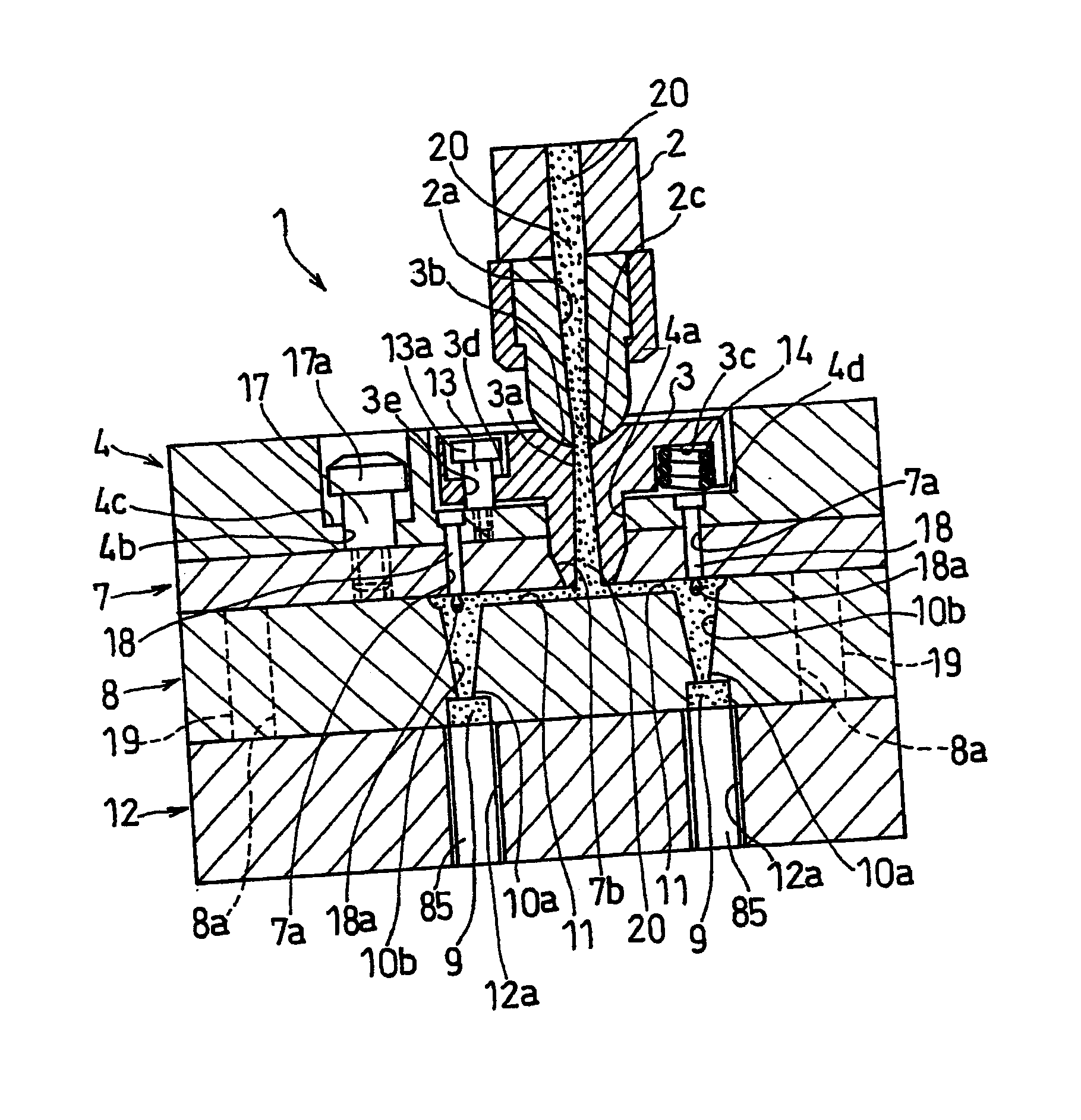
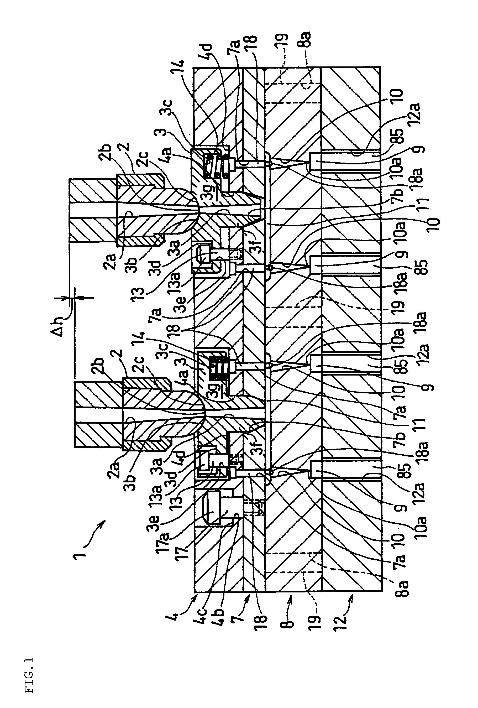
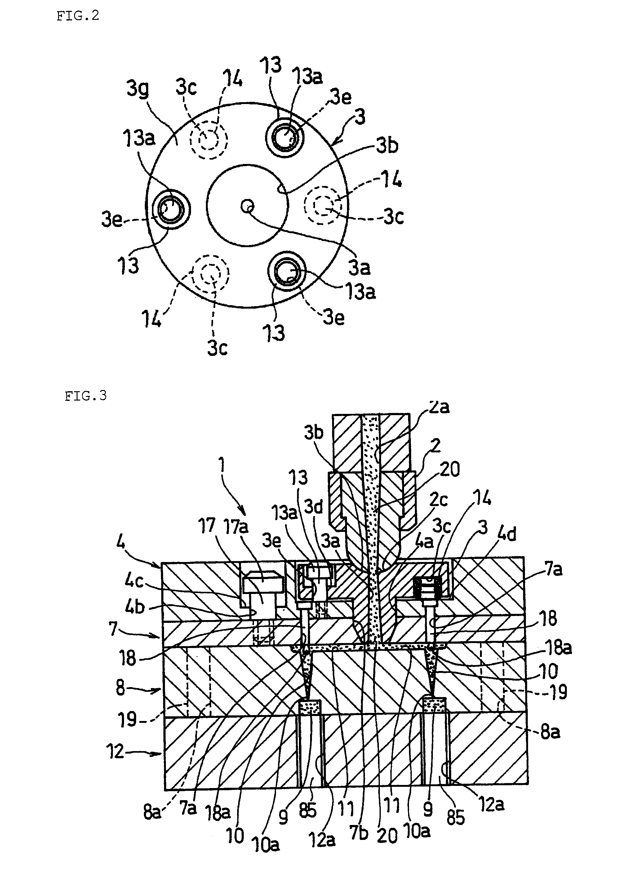
[0096]Embodiments of the invention are hereinafter described with reference to drawings. First, in order to facilitate understanding, a battery pack produced by the production method and apparatus of the invention is described. As an example of the battery pack, a battery pack using a flat, prismatic lithium ion secondary battery for use as the power source for a cell phone is described.

[0097]FIG. 9A to FIG. 9D illustrate a sequence of steps showing a part of the production process of a battery pack intermediate product (battery pack components) comprising a lithium ion secondary battery (hereinafter referred to as simply a secondary battery) and a circuit board which are integrally jointed together. A secondary battery 63 illustrated in the figure is composed of: an aluminum battery can 64 made of a cylinder having a bottom and a flat, oval cross-sectional shape; and power generating elements (not shown) contained therein. The opening of the battery can 64 is sealed by laser weldin...

embodiment 2

[0158]Embodiment 2 of the invention is hereinafter described. Since Embodiment 2 is an alteration of Embodiment 1, the differences from Embodiment 1 are mainly described below.

[0159]In Embodiment 2, instead of the step of FIG. 6 of Embodiment 1, a step which will be described with reference to FIG. 8A and FIG. 8B is performed. That is, when the solidified resin 23 is strongly bonded to the inner surface of the sprue 3a by the strong adhesive power of the molding material, lifting up the sprue bushing 3 in one stroke may cause breakage even if it is lifted up only for the distance d for applying such a tensile stress that the solidified resin 23 does not break. Thus, the elasticity of the push-up springs 14 is set to such elasticity that the sprue bushing 3 cannot be pushed up integrally with the bushing holder 4 when the bushing holder 4 lifts up from the state of FIG. 5. As a result, as illustrated in FIG. 8A, when the bushing holder 4 and the nozzle 2 are integrally lifted up to t...

embodiment 3

[0167]Embodiment 3 of the invention is hereinafter described. Since Embodiment 3 is an alteration of Embodiment 1, the differences from Embodiment 1 are mainly described below.

[0168]In Embodiment 3, at least one of the cavity plate 8 and the sprue bushing 3 is formed from heat-treated steel as the base material, and the inner surfaces of the runners 10 and the sprues 3a provided therein are formed so as to have a surface roughness of 10 to 100 μm by electrical discharge machining.

[0169]In the runner 10, the solidified resin 21 is strongly bonded to the inner surface of the runner 10, so it usually has poor mold releasability. However, in Embodiment 3, since the inner surface of the runner 10 is formed so as to have a surface roughness of 10 to 100 μm, the mold releasability of the solidified resin 21 from the runner 10 is improved. As a result, even if the solidified resin 21 is subjected to a strong lift-up force by the locking part 18, it does not break halfway and is separated fr...


PUM

PropertyMeasurementUnit
surface roughnessaaaaaaaaaa
thicknessaaaaaaaaaa

Abstract

A tensile stress is applied to solidified resin. The tensile stress is so small that the solidified resin formed in the sprue by solidification of molding material does not break and is so large that the solidified resin formed in the sprue is separated from the inner surface of the sprue due to a reduction in the diameter of the cross sectional area thereof. For the application of such a tensile stress, the runner stripper plate holding the solidified resin is moved away from the nozzle and sprue bushing. This state is maintained for a predetermined time to separate the solidified resin from the inner surface of the sprue.

Description

TECHNICAL FIELD[0001]The invention relates to a method and apparatus for producing a battery pack comprising a secondary battery and a circuit board which are integrally joined with a resin molded part and coated with a resin film.BACKGROUND ART[0002]Portable electronic devices such as cell phones and PDAs are becoming significantly smaller, thinner, and more sophisticated. Accordingly, batteries for use as the power source therefor are also required to be smaller, thinner, and higher in capacity. Promising batteries which permit small size and high capacity are lithium ion secondary batteries. Among them, flat and prismatic ones are suitable for thinning devices. Thus, such prismatic lithium ion secondary batteries are increasingly used as the power source for portable electronic devices as mentioned above.[0003]However, lithium ion secondary batteries have high energy density and use an inflammable organic solvent as the electrolyte, so they are more likely to encounter abnormal c...

Claims


Application Information

Patent Timeline
Patent Type & Authority Applications(United States)
IPC IPC(8): B29C45/14B29C45/22H01M50/209
CPCB29C45/2602B29C45/27B29C45/2756H01M2/1061B29C2045/388B29K2101/12B29K2105/0097B29C45/38Y02E60/10H01M50/209H01M50/00H01M50/20
Inventor GODA, YOSHIOKOYANAGI, YOSHINORI
Owner GK BRIDGE 1
Why Eureka
Try Eureka