Light source intensity control system and method

a technology of intensity control system and light source, applied in the field of illumination, can solve the problems of undesired effects in the spectral power distribution, affecting the intensity control system of led-based light sources in a complex way, and complex compensation of this

Inactive Publication Date: 2010-10-14
KONINKLIJKE PHILIPS ELECTRONICS NV
View PDF9 Cites 89 Cited by
  • Summary
  • Abstract
  • Description
  • Claims
  • Application Information

AI Technical Summary

Benefits of technology

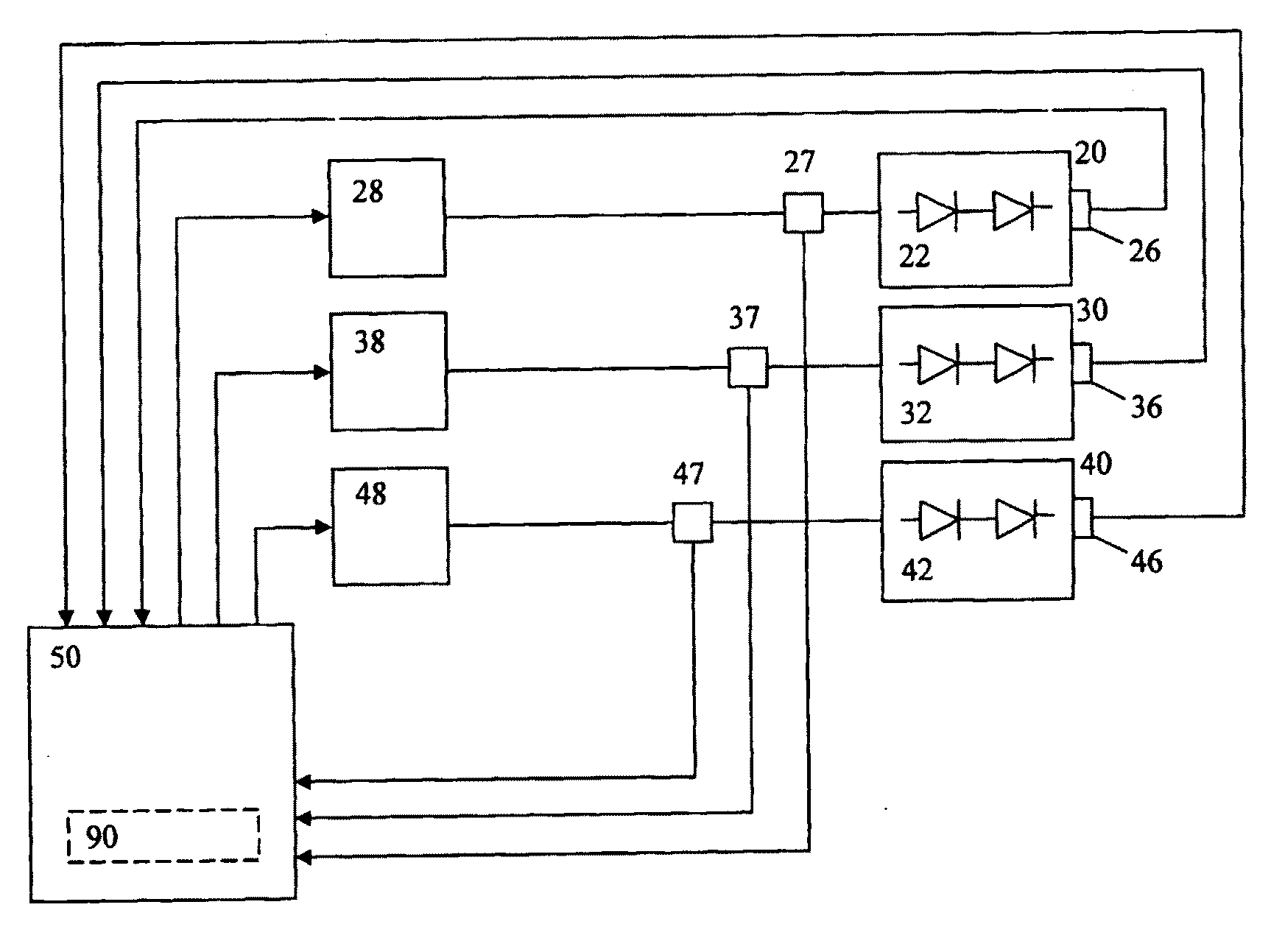
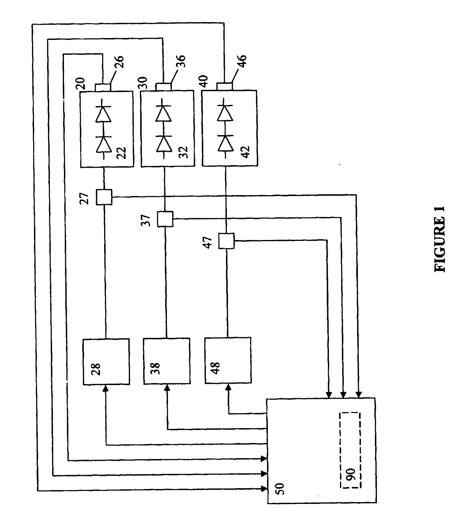
[0017]An object of the present invention is to provide a light source intensity control system and method. In accordance with an aspect of the present invention, there is provided a light source for generating a desired colour of light, said light source comprising: one or more first light-emitting elements for generating first light having a first wavelength range, the one or more first light-emitting elements responsive to a first control signal; one or more second light-emitting elements for generating second light having a second wavelength range, the one or more second light-emitting elements responsive to a second control signal; one or more sensing devices for generating one or more signals representative of operating temperatures of the one or more first light-emitting elements and the one or more second light-emitting elements; and a control system operatively coupled to the one or more first light-emitting elements, the one or more second light-emitting elements and the one or more sensing devices, the control system configured to receive the one or more signals and configured to determine the first control signal and the second control signal based upon the operating temperatures and the desired colour of light; wherein the first light and the second light are blended to create the desired colour of light.

Problems solved by technology

In spite of their success, LED-based light sources can be affected by a number of parameters in a complex way.
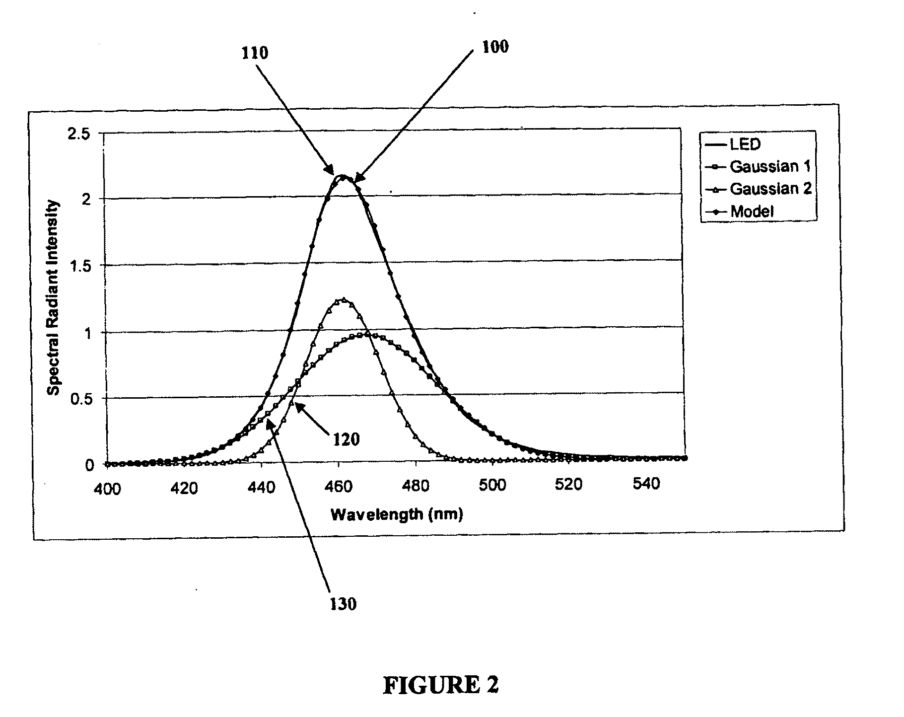
Chromaticity and luminous flux output of LEDs can greatly depend on junction temperature, which can have undesirable effects on the CCT and more generally the chromaticity of the emitted light.
However, changes in the average forward current can affect the junction temperature of the LED, which can alter the spectral power distribution and in consequence the CCT or chromaticity and luminous flux of the light emitted by the LED.
The compensation of this effect can become complex when various coloured LEDs are used to generate mixed light of a desired chromaticity.
LED junction temperature variations can also cause undesired effects in the spectral power distribution of the resultant output light.
Variations in junction temperature not only can reduce the luminous flux output, but can also cause undesirable variations in the CCT of the mixed light.
Furthermore, overheating of LEDs can also reduce the life span of LEDs.
While the Nishimura reference provides a way to achieve control of the spectral power distribution of the output light with a desired colour property, it uses a complex optical feedback system.
The calculations as required by Muthu for the mathematical transformations can, however, make it difficult to implement an optical feedback control system with a response time that is fast enough to avoid visual flicker during dimming operations, for example.
Based on this configuration, as with some previously identified prior art, the calculations required for the mathematical transformations can make it difficult to implement an optical feedback control system with a response time that is fast enough to avoid visual flicker during dimming operations, for example.
While the Schuurmans reference provides a way to achieve control of the spectral power distribution of the output light with a desired colour property, it also uses a complex optical feedback system.
In addition, a drawback of this procedure as disclosed by Muthu et al. is the excessive amount of thermal stress imposed on the LEDs during ON and OFF cycles at low frequencies which are required for the optical feedback system.

Method used


Image

  • Light source intensity control system and method
  • Light source intensity control system and method
  • Light source intensity control system and method

Examples


examples

[0080]A light source configured according to an embodiment of the present invention, was tested in order to evaluate the functionality of the light source. This embodiment of the light source comprised a defined LED cluster, a sensing device and a control system including a temperature-modified spectral radiant intensity model for each colour of LED. This light source was allowed to thermally stabilize at its respective full intensity and the CCT of the emitted light was set at 3000 Kelvin by adjusting the LED drive currents. Subsequently the LED cluster was de-energized and placed in an environmental chamber for cooling the PCB and attached heat sink to −10° C. The LED cluster was then energized and chromaticity measurements were performed as the temperature of the heat sink stabilized. The respective CCTs and CCT deviations at each temperature are shown in Table 4. In this table, the “CCT Δuv” values represent the deviation from 3000 K along the blackbody locus (corresponding to t...


PUM


Abstract

The light source comprises one or more first light-emitting elements for generating light having a first wavelength range and one or more second light-emitting elements for generating light having a second wavelength range. The first light-emitting elements and second light-emitting elements are responsive to separate control signals provided thereto. A control system receives a signal representative of the operating temperature from one or more sensing devices and determines first and second control signals based on the desired colour of light and the operating temperature. The light emitted by the first and second light-emitting elements as a result of the received first and second control signals can be blended to substantially obtain the desired colour of light. The desired colour of light generated can thus be substantially independent of junction temperature induced changes in the operating characteristics of the light-emitting elements.

Description

FIELD OF THE INVENTION[0001]The present invention pertains to the field of illumination and in particular to an intensity control system for a light source.BACKGROUND[0002]Recent advances in the development of semiconductor light-emitting diodes (LEDs) and organic light-emitting diodes (OLEDs) have made these devices suitable for use in general illumination applications, including architectural, entertainment, and roadway lighting, for example. As such, these devices are becoming increasingly competitive with light sources such as incandescent, fluorescent, and high-intensity discharge lamps.[0003]Due to its natural lighting characteristics, white light is typically the preferred choice for lighting. An important consideration for LED-based luminaires used for ambient lighting and LED-based backlighting for liquid crystal displays (LCDs) is the need to produce natural white light. White light can be generated by mixing the light emitted from different colour LEDs.[0004]Various stand...

Claims


Application Information

Patent Timeline
Patent Type & Authority Applications(United States)
IPC IPC(8): H05B37/02H01L33/00H05B44/00
CPCH05B33/0863H05B33/0872H05B33/0869H05B45/28F21Y2115/10H05B45/20H05B45/22H05B45/46
Inventor MAN, KWONGASHDOWN, IAN
Owner KONINKLIJKE PHILIPS ELECTRONICS NV
Why Eureka
Try Eureka