
Method and System for Determining the Orientation of an Ophthalmic Lens

a technology of ophthalmology and orientation, applied in the field of method and system for determining the orientation of ophthalmology, can solve the problems of not being strictly useful for users with already impaired vision, not allowing oxygen to pass through the lens to the eye, and not being able to readily distinguish between lenses intended for the left eye and/or the right eye, etc., to achieve significant reduction of eye damage, distortion of optical properties of lenses, and discomfort to the eye

Inactive Publication Date: 2010-10-14
SABETA ANTON
View PDF1 Cites 84 Cited by
  • Summary
  • Abstract
  • Description
  • Claims
  • Application Information

AI Technical Summary

Benefits of technology

[0015]In another of its aspects the present invention provides a method and system for determining the orientation of an optical device. The optical device comprises an anterior surface and a posterior surface, the method having the steps of providing the optical device with uniquely identifiable data carrier means for carrying data related to the optical device, the data carrier comprising a device operable in at least one of an electrical mode and a magnetic mode; the data carrier means being deposited on at least one of a posterior surface, an anterior surface, and an edge surface; causing the data carrier means to emit a data signal; processing the emitted data signal to determine the characteristics the emitted data signal, and hence the orientation of the lens. For example, a user can readily determine the eye contacting surface of a contact lens prior to insertion.
[0019]In another of its aspects the present invention provides a method and system, and a method of manufacturing thereof, for a contact lens having an optical power which varies radially and circumferentially about the optic axis of the lens comprising data carrier means associated with the lens, the data carrier being disposed in the peripheral portion of the lens adjacent the periphery and along at least one axis of the lens, or the data carrier being disposed in a predetermined position as a marker, to cause the lens to maintain a predetermined orientation upon the eye of a wearer and consistently maintain a preferred orientation upon the eye of a wearer based on the location of the data carrier means marker on the lens.
[0020]Advantageously, by having the correct orientation of lens, problems such as distortion of the optical properties of the lens, and discomfort to the eye, and eye damage, are significantly diminished.

Problems solved by technology

In contrast, hard contact lenses are made of a hard plastic material, such as polymethyl methylacrylate (PMMA), which does not allow oxygen to pass through the lens to the eye.
One issue facing lens wearers, eyecare practitioners, and the industry, has been the inability to readily distinguish between lenses intended for the left eye and / or the right eye.
However, these methods depend on the visual inspection of the lenses by the user in order to interpret the markings, which is not strictly useful for a user with already impaired vision, and thus may be undecipherable.
Also, these identification methods are manufacturing intensive, and require the use of expensive equipment.
Yet another problem facing users and the industry is the inability to readily determine which surface of the lens should be disposed against the eye.
This problem has been further exacerbated by the development of newer polymers for soft contact lenses, in which the thickness of the lenses has been steadily reduced to the point where the lenses can easily end up being inside out, instead of right side out.
In this orientation the lens can distort the optical properties of the lens, and may cause discomfort to the eye and in some instances can result in eye damage.
It is clear that these methods are subjective, time-consuming, and may even be frustrating to a user, while still presenting a substantially low chance for correct lens orientation determination.
Further, certain types of defects in the eye can only be corrected by lenses which are not spherical.
Misalignment errors will prevent proper correction of astigmatism.
However, because of irregularities in the shape of the cornea, interference by the lower lid, the lens does not stay in its preferred orientation, and may settle to a position that is rotated 5 or more degrees from its intended position.
However, such a method is uncomfortable for the user who is subjected to looking at the light, and decentralization of the pupil with respect to the center of the cornea, or of the lens with respect to the center of the cornea, or both can cause the measurement to be inaccurate.

Method used


Image

  • Method and System for Determining the Orientation of an Ophthalmic Lens
  • Method and System for Determining the Orientation of an Ophthalmic Lens
  • Method and System for Determining the Orientation of an Ophthalmic Lens

Examples


Embodiment Construction

[0032]The following detailed description is merely exemplary in nature and is not intended to limit the invention or the application and uses of the invention. Furthermore, there is no intention to be bound by any expressed or implied theory presented in the preceding technical field, background, brief summary or the following detailed description.

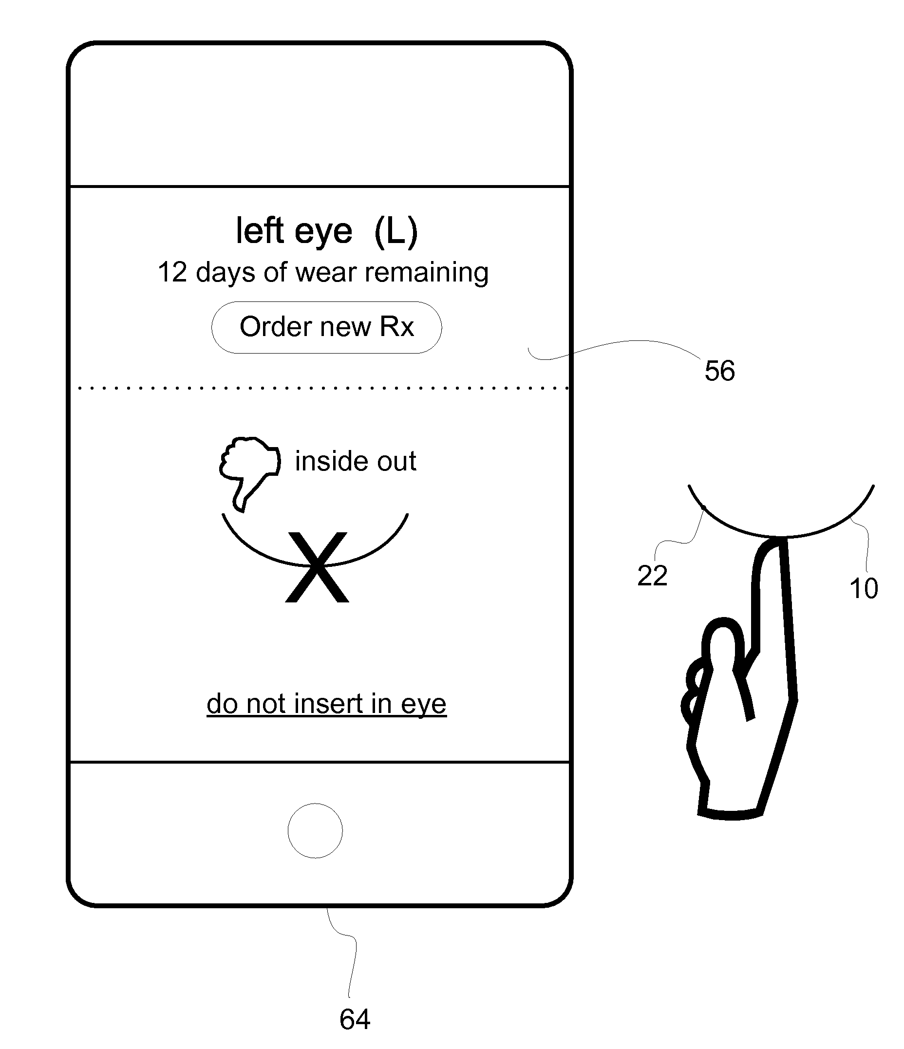
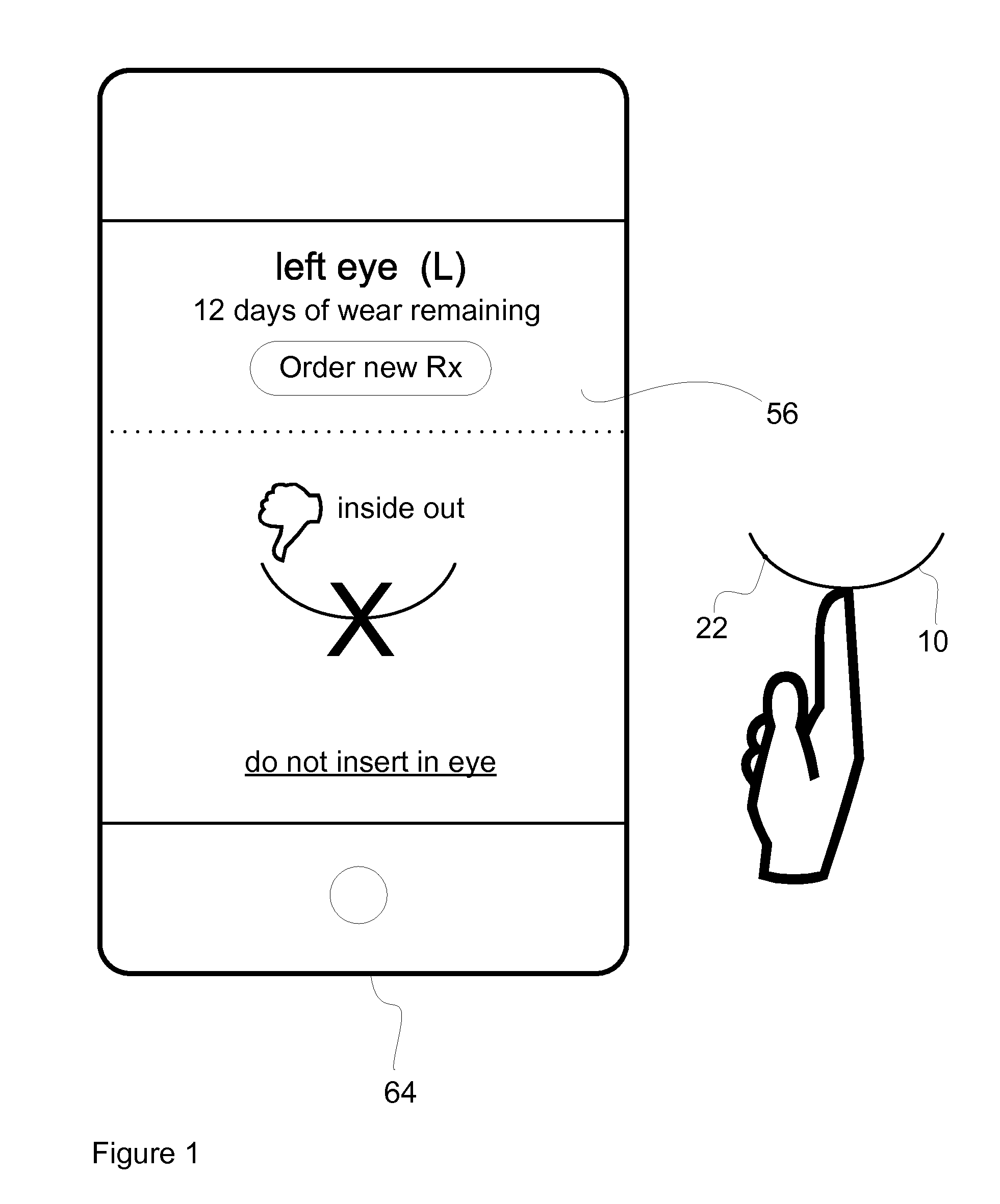
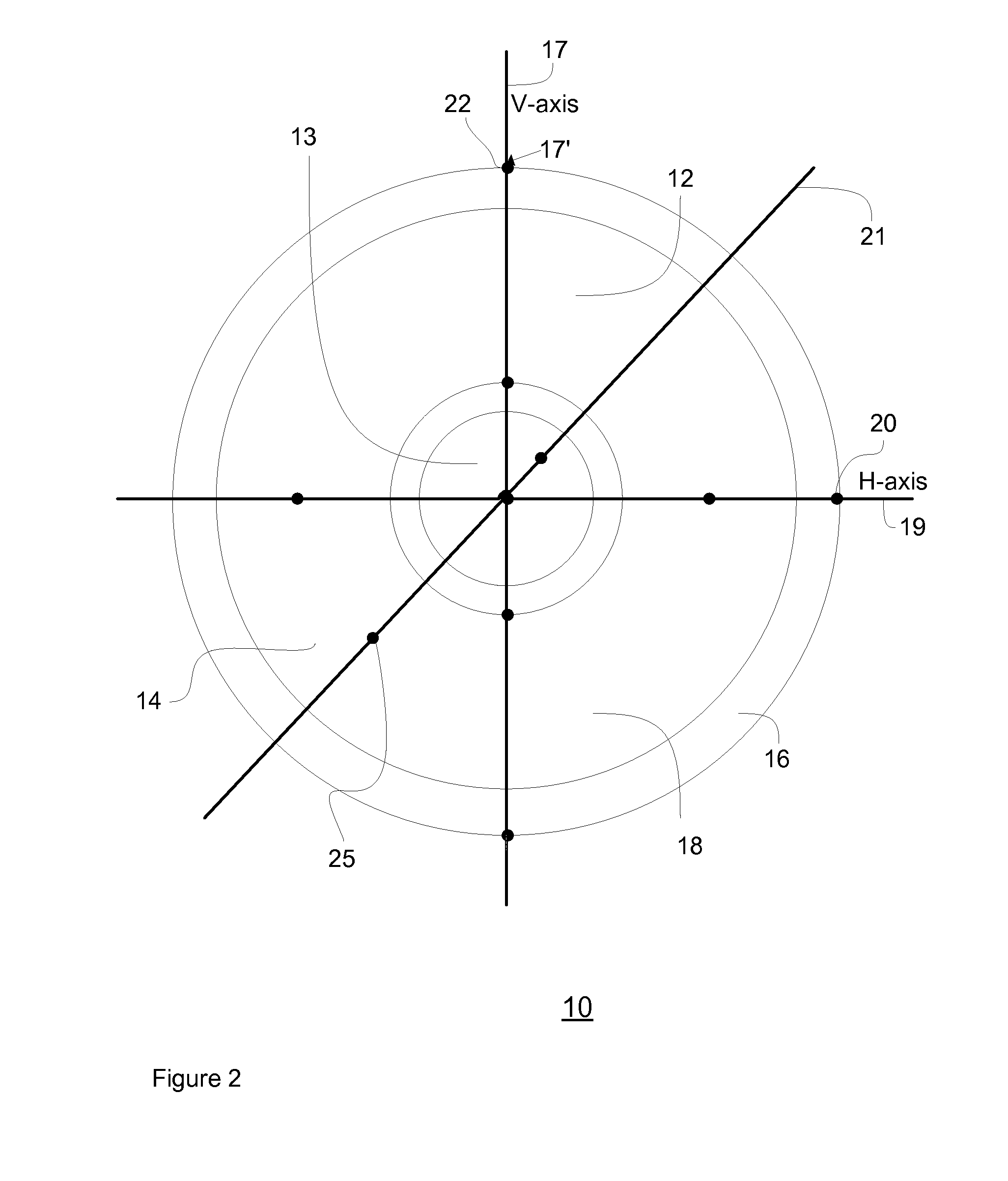
[0033]Referring to FIGS. 1 and 2, there is shown an optical device 10 having features for characterization thereof, such as an ophthalmic device, in an exemplary embodiment of the present invention. The ophthalmic device 10, as disclosed in the exemplary embodiments, includes, but is not limited to, ophthalmic lenses, soft contact lenses, hard contact lenses, bifocal contact lenses, multi-focal contact lenses, colored contact lenses, disposable contact lenses, extended wear contact lenses, gas permeable (GP) contact lenses, rigid gas permeable (RGP) contact lenses, monovision lenses, orthokeratology lenses, prosthetic contact lenses, silic...


PUM


Abstract

A method and system for determining the orientation of an ophthalmic lens for assisting a user to readily determine the eye contacting surface of the ophthalmic lens prior to insertion into the eye.

Description

CROSS-REFERENCE TO RELATED APPLICATIONS[0001]This application is a Continuation-in-Part of, and claims the benefit from U.S. application Ser. No. 12 / 578,564, filed on 13 Oct. 2009, which is a Continuation of Ser. No. 11 / 562,981 filed on 22 Nov. 2006, the contents of each which are incorporated herein by reference.BACKGROUND OF THE INVENTION[0002]1. Field of the Invention[0003]The present invention relates to a method and system for determining the orientation of an ophthalmic lens.[0004]2. Description of the Prior Art[0005]Optical components are items that are used to bend, split, diffuse, reflect or otherwise alter or refocus light wavelengths. These optical components are usually formed from a piece of shaped glass or plastic, among other materials. Optical light sources include astronomical objects, or devices that produce or radiate light when excited, such as, lasers, diodes, and lamps. The light produced can be in the visible range, the infrared range or ultraviolet ranges, of...

Claims


Application Information

Patent Timeline
IPC IPC(8): G02C7/04G06K7/00G06Q30/00
CPCA45C11/005G06Q30/0601G02B27/62
Inventor SABETA, ANTON
Owner SABETA ANTON
Learn More