Multi-electrode strung on a common connector

a technology of multi-electrodes and connectors, applied in the field of electrodes, can solve the problems of irritating the skin of patients, affecting the electrode flexibility, rash or burning sensation, etc., and achieve the effect of facilitating the manufacture of electrodes and facilitating the manufactur

Active Publication Date: 2010-10-14
AXELGAARD MANUFACTURING COMPANY INC
View PDF8 Cites 28 Cited by
  • Summary
  • Abstract
  • Description
  • Claims
  • Application Information

AI Technical Summary

Benefits of technology

[0006]The present invention is directed to a medical electrode having a combination of conductive elements, with selected conductivities which enables assembly of the electrode in a manner hereinbefore not possible. More specifically, the present invention is directed to a medical electrode having a connector disposed on a top surface of a conductive member. This enables automated assembly of the electrode as opposed to conventional manual assembly which in turn reduces unit cost while at the same time providing for controlled and even current density. Interconnection of multiple electrodes may be effected through the use of a leadwire having alternating conductive and non-conductive portions.SUMMARY OF THE INVENTION
[0009]The use of a moderately high conductivity adhesive enables the placement of a connector on the top side of the flexible member while at the same time providing uniform current distribution by the electrode.
[0011]The connector is disposed over the conductive ink pattern and on the top side of the conductive member, whereas the ink pattern is disposed on the bottom side of the conductive member. This arrangement enables the connectors to be disposed in any selected points within a perimeter of the pattern without affecting current distribution. This flexibility of connector positioning, provided by the present invention, facilitates manufacture of the electrodes. In addition, because the lead wire is not disposed between the conductive pattern and patients' skin, there is no interference with the electrode current distribution as is the case with some prior art electrodes.
[0013]A non-conductive flexible sheet may be disposed over the connector on the conductive flexible member top side. The non-conductive flexible sheet preferably has dimensions greater than said conductive flexible member causing an overlap thereof. This arrangement facilitates manufacture and also eliminates the need for precise alignment with the conductive flexible member. It also provides a seal of the gel edge and prevents gel from folding around an edge of the conductive flexible member and attaching itself to clothing, etc.

Problems solved by technology

It is well known that inadequate flexing and shaping of the electrode to a patient's contour can result in an irritation of the patient's skin.
Electrical “hot spots” due to uneven electrode-skin contact can result in a rash or a burning sensation.
Many prior art electrodes have compromised the flexibility of the electrode in order to provide adequate current densities over the entire contact area of the electrode.
Such use of foil or mesh often cause burning or hot spots at electrode edges.

Method used


Image

  • Multi-electrode strung on a common connector
  • Multi-electrode strung on a common connector
  • Multi-electrode strung on a common connector

Examples


Embodiment Construction

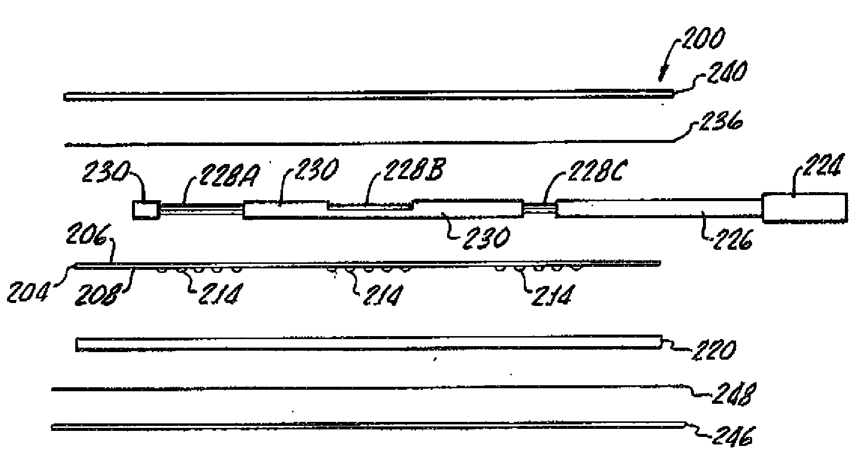
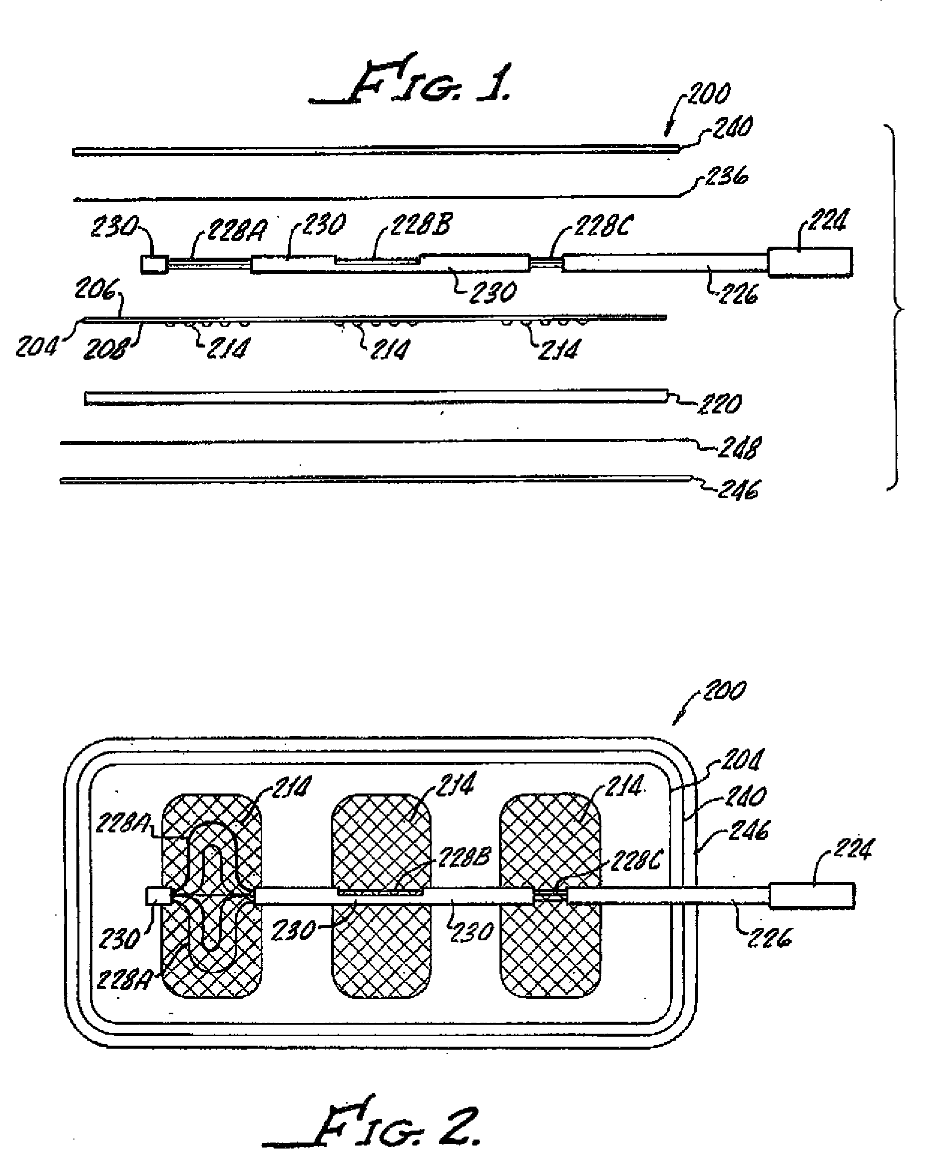
[0020]With reference now FIGS. 1 and 2 there is shown an electrode 200 which includes a moderately conductive flexible member 204, such as, for example, a carbon film, having a top side 206 and a bottom side 208. A plurality of highly conductive patterns 214 are disposed on the bottom side 208 of the conductive flexible member 204. The patterns are disposed in a spaced apart relationship, as shown, and while only three (3) patterns are shown, any suitable number may be used.

[0021]As shown, a moderately high conductive adhesive layer 220 is disposed on the conductive flexible member bottom side 208 and covers the conductive patterns 214 while also functioning to adhere the electrode 200 to a patient's skin, not shown. Alternatively, the conductive adhesive layer 220 may be disposed on the conductive flexible member top side 206.

[0022]A connector 224 provided for interconnecting the conductive patterns 214 establishes electrical contact with an external apparatus, not shown. The conne...


PUM


Abstract

A medical electrode includes a moderately conductive flexible member having a top side and a bottom side with a plurality of highly conductive patterns disposed on the conductive flexible member bottom side in a spaced apart relationship. A moderately highly conductive layer disposed on the conductive flexible member bottom side and covering the conductive patterns, for adhering the electrode to a patient's skin. A connector is provided for establishing electrical contact with an external apparatus. The connector includes a leadwire having conductive portions in electrical communication with the conductive patterns and non-conductive portions between the conductive patterns. Control over conductivity between the leadwire conductive portion and the conductive pattern is provided.

Description

[0001]The present invention generally relates to electrodes and, more particularly, electrodes suitable for transcutaneous nerve and / or muscle stimulation and biological signal recording.[0002]Medical electrodes must provide an even electrical distribution to a patient's skin over an entire surface of the electrode to assure proper coupling. Because of the curvaceous nature of the human body, it is apparent that medical electrodes for use thereon must be flexible not only for confirmation with a patient's skin contours, but also to accommodate relative movement of the patient's skin.[0003]It is well known that inadequate flexing and shaping of the electrode to a patient's contour can result in an irritation of the patient's skin. Electrical “hot spots” due to uneven electrode-skin contact can result in a rash or a burning sensation. A sensation of burning may be felt by a patient within a few minutes after application of the electrical signals during nerve and / or muscle stimulation,...

Claims


Application Information

Patent Timeline
Patent Type & Authority Applications(United States)
IPC IPC(8): A61B5/04A61N1/04
CPCA61B5/04085A61N1/0452A61N1/0492A61N1/0476A61N1/048A61N1/0456A61B5/282
Inventor AXELGAARD, JENS
Owner AXELGAARD MANUFACTURING COMPANY INC
Why Eureka
Try Eureka