
Induced-charge electrokinetics with high-slip polarizable surfaces

a polarized surface, electrokinetic technology, applied in electrodialysis, diaphragms, refrigeration components, etc., can solve the problems of limiting the flow rate in some applications, affecting the electrodynamics of the electrodynamics, and the salt concentration of the fluid must be relatively low (10 mm) to achieve the effect of rapid electroosmotic flows and enhanced electrophoretic mobility

Inactive Publication Date: 2010-10-21
MASSACHUSETTS INST OF TECH
View PDF4 Cites 19 Cited by
  • Summary
  • Abstract
  • Description
  • Claims
  • Application Information

AI Technical Summary

Benefits of technology

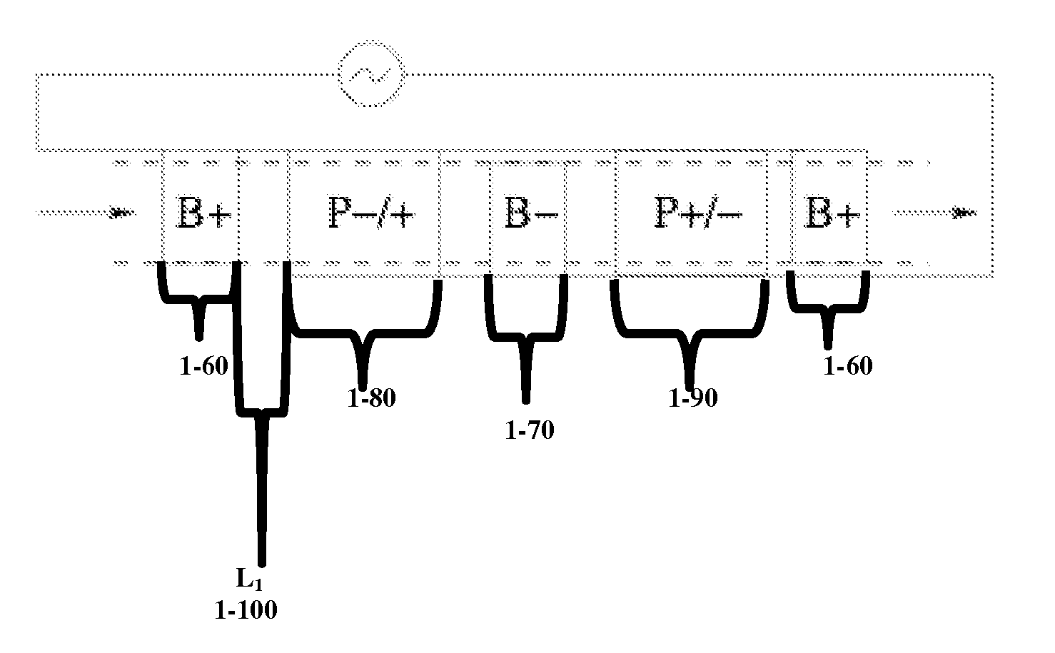
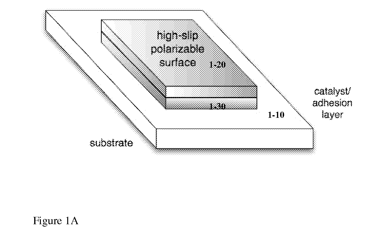
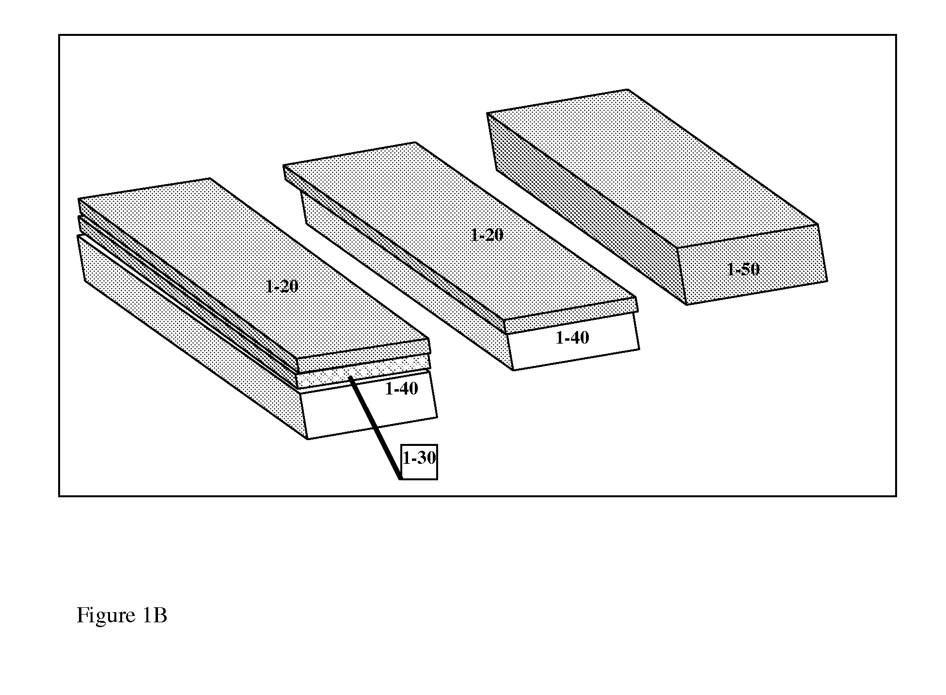
[0008]The present invention, in some embodiments, makes use of high-slip polarizable (HSP) surfaces in induced-charge electrokinetic applications for the generation of rapid electroosmotic flows and enhanced electrophoretic mobility.
[0044]In another embodiment, there may be multiple chambers comprising the device, where fluid transport between two or more of the chambers is controlled by said method of induced-charge electro-osmotic flow. In another embodiment, there may be additional means of generating flow within or between the chambers, e.g. using pressure gradients or DC electro-osmotic flow, which are augmented by said method of induced-charge electro-osmotic flow to enhance pumping or mixing of said fluid.

Problems solved by technology

In some cases, however, the flows generated are not fast enough for efficient pumping or separation.
ICEO-based devices have achieved flow rates with mm / sec velocities, but viscous drag away from the pump and the small pressures generated (<100 Pa=0.001 atm) can limit the flow rate in some applications.
In manipulating biological molecules, reagents, markers, and cells by ICEP or pumping biological fluids by ICEO in current devices, another potential limitation is that the salt concentration of the fluid must be relatively low (100 mM).

Method used


Image

  • Induced-charge electrokinetics with high-slip polarizable surfaces
  • Induced-charge electrokinetics with high-slip polarizable surfaces
  • Induced-charge electrokinetics with high-slip polarizable surfaces

Examples


example 1

Enhanced Induced-Charge Electro-Osmotic Flow in Devices with High Slip Polarizable Surfaces

[0320]It will be clear to the skilled artisan that there are many devices and methods which may apply the use of HSP surfaces to drive ICEO / ACEO fluid flows in microfluidic devices. For example, and in some embodiments, the invention can be applied to electrode surfaces for AC electro-osmotic microfluidic devices, polarizable surfaces (free or fixed-potential) for more general ICEO devices, and gate-electrode surfaces for flow-FETs. All of these types of microfluidic devices with HSP surfaces can be used for fluid pumping, sample mixing, and / or trapping suspended particles, as described in the prior art cited above.

[0321]One embodiment of a device of this invention comprises a device on which at least one surface of the device, or in some embodiments, one surface of a component of the device, for example a conductor or microfluidic pump, or an electrode, comprises a high slip polarizable (HSP)...

example 2

Embodiments of ICEO Devices with HSP Surfaces

[0337]In another embodiment, ICEO devices, such as those described in Example 1, comprise HSP surfaces which contain carbon nanostructures, such as nanotubes (CNT), which can be single-walled or multi-walled, or in some embodiments, in the form of other fullerene structures, such as, and in some embodiments, nanohorns, nanobuds, buckyballs, or fullerite. The surfaces of such nanostructures resemble curved graphene sheets and are typically hydrophobic.

[0338]According to this aspect of the invention, and in some embodiments, the complex structures, as for the coating, display significant slip lengths. For example, metallic single-wall CNT have been reported to have very large slip lengths (up to 100 nm outside, up to 1 micron inside). Double-wall CNT retain similar properties but are more resistant to damage from impurity adsorption. The hydrodynamic slip length on the outer side of a CNT is typically much larger in the direction parallel t...

example 3

ICED Devices Comprising HSP Patterned Surfaces

[0344]In pressure-driven flows, effective slip can be enhanced over a patterned surface by incorporating non-wetting or liquid-phobic regions of high interfacial tension between the solid and liquid, as described above, and / or by structures promoting the formation of micro / nano-bubbles. The former is one mechanism to achieve enhanced molecular-level slip, as described above in the case of carbon. The latter can nucleate gas bubbles at surface cracks or engineered patterns of peaks and valleys, such that the fluid de-wets and forms a liquid-gas interface stretching over the valleys from peak to peak. According to this aspect and in some embodiments, high gas saturation is needed in the liquid. In some embodiments, the liquid-gas interface over a bubble is a zero stress boundary, which reduces the overall hydrodynamic resistance of the surface.

[0345]In some embodiments, this invention is directed to the use of, and devices incorporating a ...


PUM

PropertyMeasurementUnit
Lengthaaaaaaaaaa
Fractionaaaaaaaaaa
Fractionaaaaaaaaaa

Abstract

This invention provides devices and apparatuses comprising the same, for fast pumping and mixing of relatively small volumes of electrolytes and ionic fluids and materials suspended thereby. Such devices utilize nonlinear induced-charge electro-osmosis as a primary mechanism for driving fluid flow. Such devices comprise a polarizable surface, which is incorporated in the electrodes or pumping elements of the devices as well as a material, which promotes hydrodynamic slip at a region proximal thereto, when the device is subjected to non-linear electro-osmotic flow. Examples of such materials are provided. This invention also provides nanoparticles and microparticles incorporating such materials to enhance nonlinear induced-charge electrophoretic motion. Methods of use of the devices and particles of this invention are described.

Description

GOVERNMENT SUPPORT[0001]This invention was made in whole or in part with U.S. Government support from the Institute for Soldier Nanotechnologies, US Army Research Office, Grant Number DAAD-19-02-D002. The government has certain rights in the invention.BACKGROUND OF THE INVENTION[0002]Nonlinear electrokinetic phenomena involve the motion of a fluid or suspended particles in response to an applied electric field, where the motion depends nonlinearly on the field strength (typically as the square, at low voltage). In electrolytes, the fundamental effect is “induced-charge electro-osmosis” (ICEO), the action of an electric field on its own induced-charge in the electrochemical double layer.[0003]ICEO flows around polarizable (dielectric, metallic, or ion conducting) particles have been used to manipulate asymmetric metal particles in microdevices, by “induced-charge electrophoresis” (ICEP). Recent examples include the alignment of bimetallic (silver / gold) rod-like nano-barcode particles...

Claims


Application Information

Patent Timeline
IPC IPC(8): G01N27/26
CPCB01L3/50273B01L2300/165B01L2300/166F04B19/006B01L2400/0421F04B15/00F04B17/00B01L2400/0418
Inventor BAZANT, MARTIN Z.
Owner MASSACHUSETTS INST OF TECH
Learn More