Cell capture chip based on induced charge electroosmosis induced by rotating electric field
A technology of inductive charge and rotating electric field, applied in stress-stimulated microbial growth methods, biomass post-processing, biochemical equipment and methods, etc., can solve the problems of inappropriate capture size Joule heat, etc., and achieve high-efficiency single capture, conductivity The effect of low and low voltage
- Summary
- Abstract
- Description
- Claims
- Application Information
AI Technical Summary
Problems solved by technology
Method used
Image
Examples
specific Embodiment approach 1
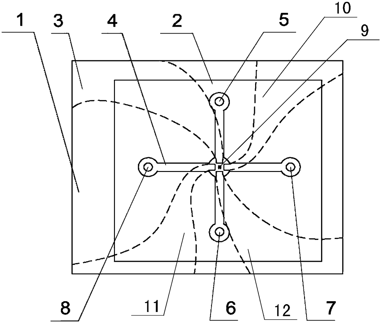
[0015] Specific implementation mode one: combine figure 1 To illustrate this embodiment, a cell capture chip based on induced charge electroosmosis induced by a rotating electric field described in this embodiment includes a glass substrate 1, a PDMS cover 2, a first excitation electrode 3, a second excitation electrode 10, a third The excitation electrode 11, the fourth excitation electrode 12 and the suspension electrode array 9;
[0016] The PDMS cover 2 is fixed on the glass substrate 1, and the glass substrate 1 is used to carry the PDMS cover 2, the first excitation electrode 3, the second excitation electrode 10, the third excitation electrode 11, the fourth excitation electrode 12 and the suspension electrode Array 9; two mutually perpendicular PDMS channels 4 are opened on the PDMS cover sheet 2; one end of a PDMS channel is provided with a main channel inlet 5, and the main channel inlet 5 is used to inject a solution containing a single cell, and the other end is pr...
specific Embodiment approach 2
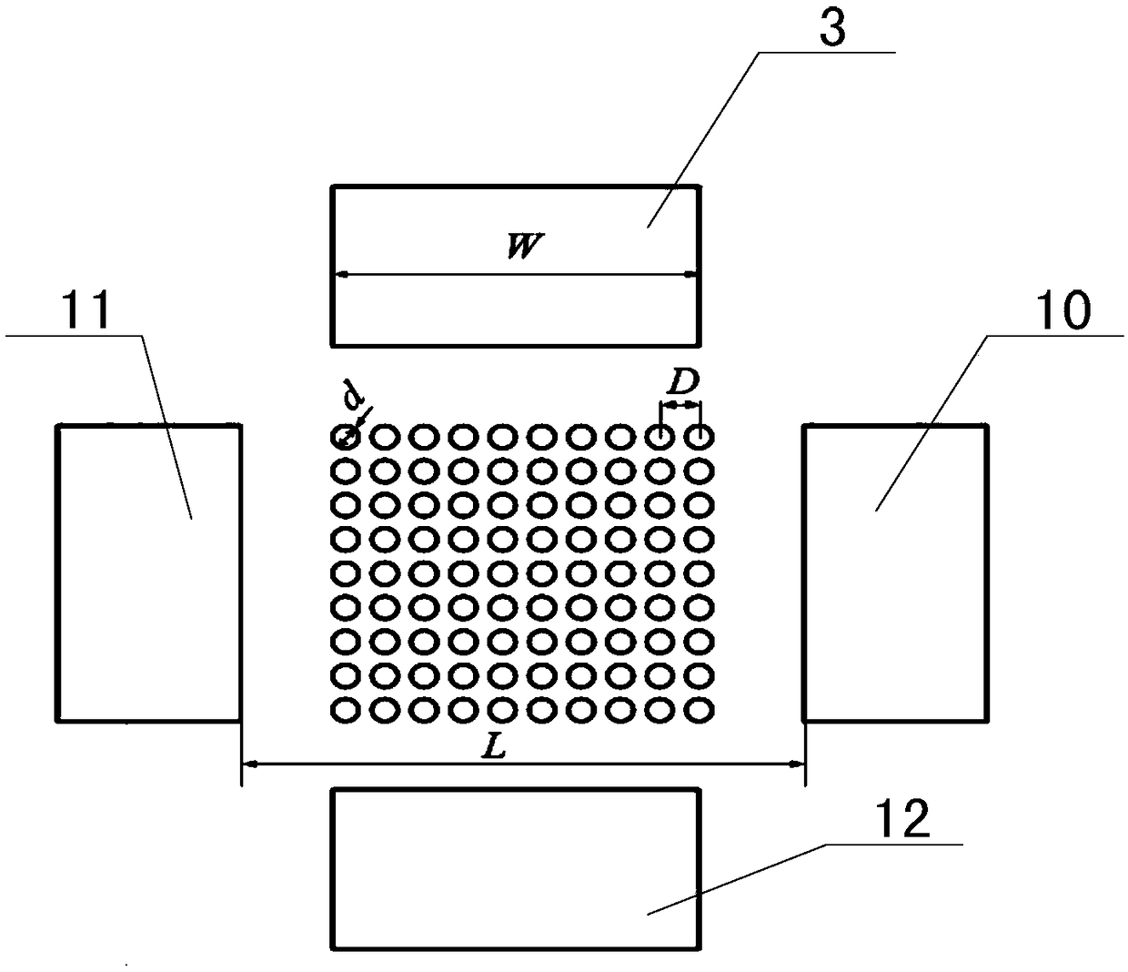
[0021] Specific implementation mode two: combination figure 2 and image 3 Describe this embodiment, this embodiment is to further limit the cell capture chip based on the induced charge electroosmosis induced by the rotating electric field described in the first embodiment, in this embodiment, the suspension electrode array 9 includes N× N floating electrodes, N×N floating electrodes are arranged in N rows and N columns, and the floating electrode array 9 is a square;
[0022] Said N is an integer greater than 3.
[0023] In this embodiment, if figure 2 As shown, the suspension electrode is a cylinder, the diameter d of the cylinder is 20 μm, and the distance D between two cylinders adjacent to each other in the same row or column is 40 μm.
[0024] During the experiment of capturing cells, first, add a certain amount of deionized water to the beaker, slowly add potassium chloride, and monitor the conductivity of the solution in real time with a conductivity meter to obt...
specific Embodiment approach 3
[0032] Specific embodiment three: this embodiment further defines the cell capture chip based on the induced charge electroosmosis induced by the rotating electric field described in the second specific embodiment. In this embodiment, the inner part of the first excitation electrode 3 The distance between the end and the inner end of the fourth exciting electrode 12 is greater than the side length of the suspended square floating electrode array 9, and the distance between the inner end of the second exciting electrode 10 and the inner end of the third exciting electrode 11 is greater than the square floating electrode array. The side length of the electrode array 9 is to ensure that the F solution can pass through the PDMS channel 4 normally.
[0033] In this embodiment, the distance between the inner end of the first excitation electrode 3 and the inner end of the fourth excitation electrode 12 is equal to the distance between the inner end of the second excitation electrode ...
PUM
 Abstract
Description
Claims
Application Information
 - R&D
- Intellectual Property
- Life Sciences
- Materials
- Tech Scout
- Unparalleled Data Quality
- Higher Quality Content
- 60% Fewer Hallucinations
Browse by: Latest US Patents, China's latest patents, Technical Efficacy Thesaurus, Application Domain, Technology Topic, Popular Technical Reports.
© 2025 PatSnap. All rights reserved.Legal|Privacy policy|Modern Slavery Act Transparency Statement|Sitemap|About US| Contact US: help@patsnap.com


