[0005]The invention provides an intervertebral
spinal implant for maintaining intervertebral spacing between and promoting the fusion together of two adjacent vertebrae. In an aspect, the intervertebral
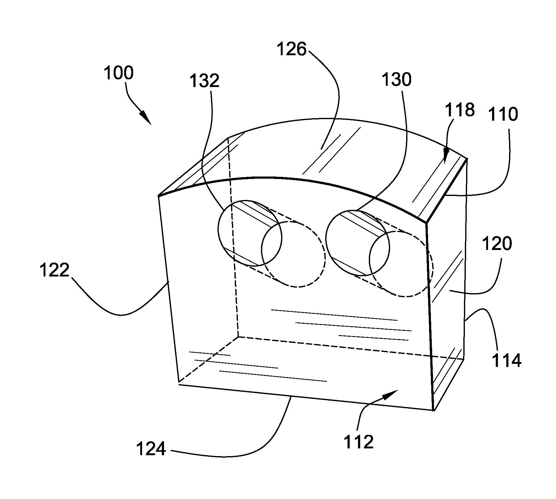
implant can have a generally flat body with a first surface and an opposing second surface that is sized and shaped for
insertion into the
intervertebral space. Disposed into the body can be at least one aperture that can be formed to receive osteogenic or similar medicinal material that promotes
bone growth between the
vertebrate to fuse those vertebrate together. To optimize retention of the osteogenic material within the body during manipulation of the implant, the aperture in some embodiments can be disposed on a non-perpendicular angle into the first surface of the body. In other embodiments, the aperture can taper or be conically shaped as it extends from the first surface toward the second surface of the body. The tapering of the aperture can be in addition to or besides disposing the apertures on non-perpendicular angles. Another
advantage of disposing the osteogenic material receiving aperture on a non-perpendicular angle or on a taper is that the material will tend not to shake or fall loose from the aperture. Another
advantage is that the non-perpendicular or tapered apertures can accommodate more osteogenic material.
[0006]In another aspect of the invention, an intervertebral implant having a flat body with first and second opposing surfaces can have disposed into at least one surface a plurality of grooves. The grooves can have any suitable shape or pattern, but preferably have a gull-wing shape. To provide the gull-wing shape, the grooves can have a first curve and a second curve that intersect together approximately mid-width of the implant. The gull-wing shaped grooves can retain osteogenic or other medicinal material and can allow for ingrowth of the
host bone. In various embodiments, the intervertebral implant can have gull-wing shaped grooves on both the first and second surface and further can include one or more osteogenic material receiving apertures of the above described kind. Another
advantage of disposing the gull-wing shaped grooves across a surface of the implant is that grooves provide traction where the
implant surface meets the vertebrae thereby preventing slipping or movement of the implant.
[0007]In another aspect of the invention, an intervertebral implant having a flat body and first and second opposing surfaces can be formed from the elongated
diaphysis or shaft portion of a long donor bone. To form the implant, a plurality of outlines, each of the first surface, are
cut or otherwise disposed directly into the outer surface of the
bone tissue such that the plurality of outlines are arranged axially along the
diaphysis. Accordingly, one surface of the implant corresponds to the outer surface of the
diaphysis of the donor bone. This is in contrast to prior art methods, in which allografts or spinal implants are typically formed by disposing cuts perpendicularly into the diaphysis. An advantage of preparing the implants by
cutting into the disphysis parallel rather than perpendicular to its
long axis is to conserve donor bone by enabling larger and more implants to be formed from a given bone.
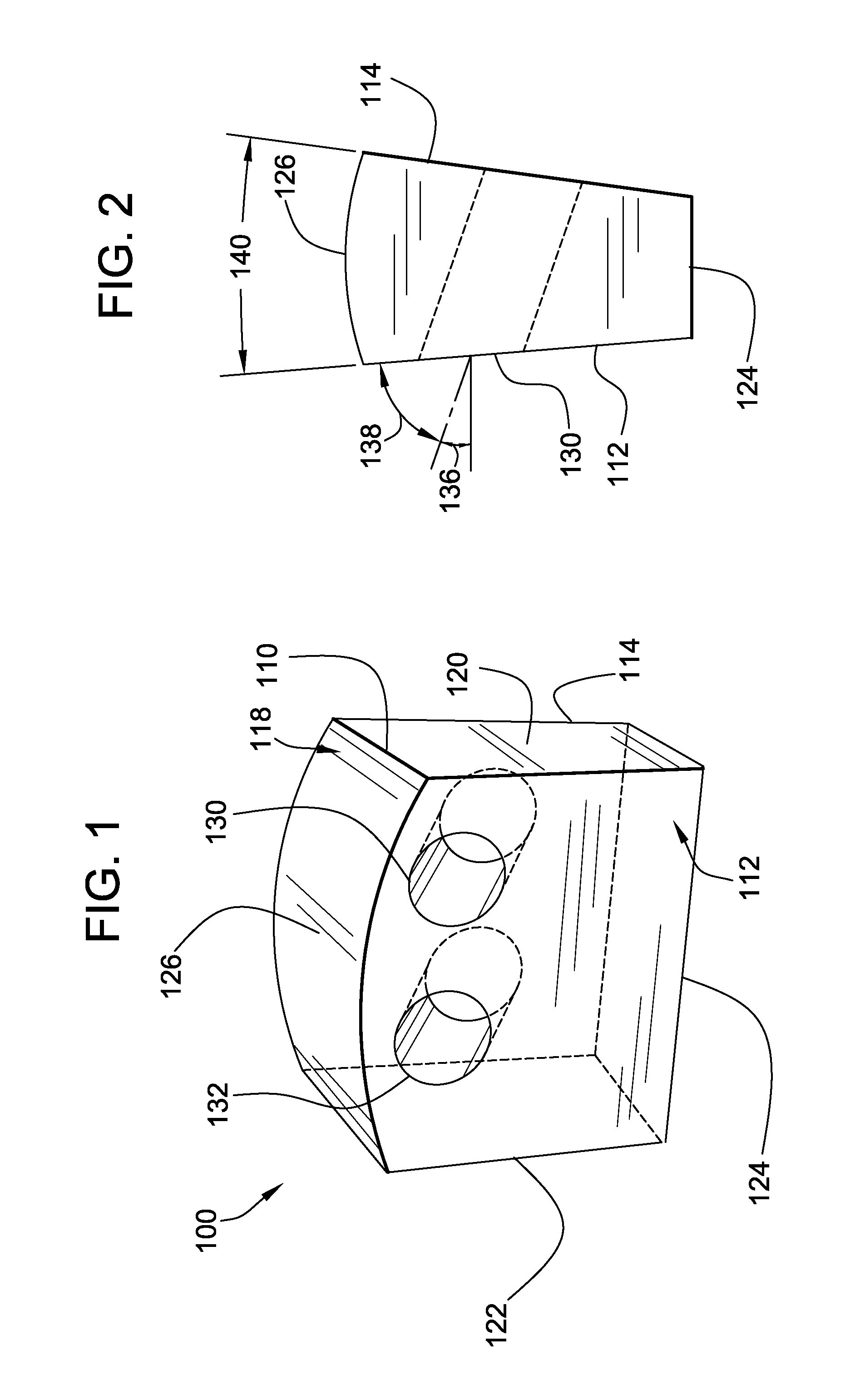
[0008]In another aspect of the invention, the intervertebral implant can have a generally flat body generally shaped overall as a
question mark. The question-mark shape can be provided by having a
peripheral surface of the body include a straight first edge, a curved second edge extending away from the first edge, and a cutout formed into the first edge. In various embodiments, the cutout can receive osteogenic or other medicinal material. An advantage of forming the implant with a question-mark shape is that such a shape helps to fill the entire
intervertebral space.
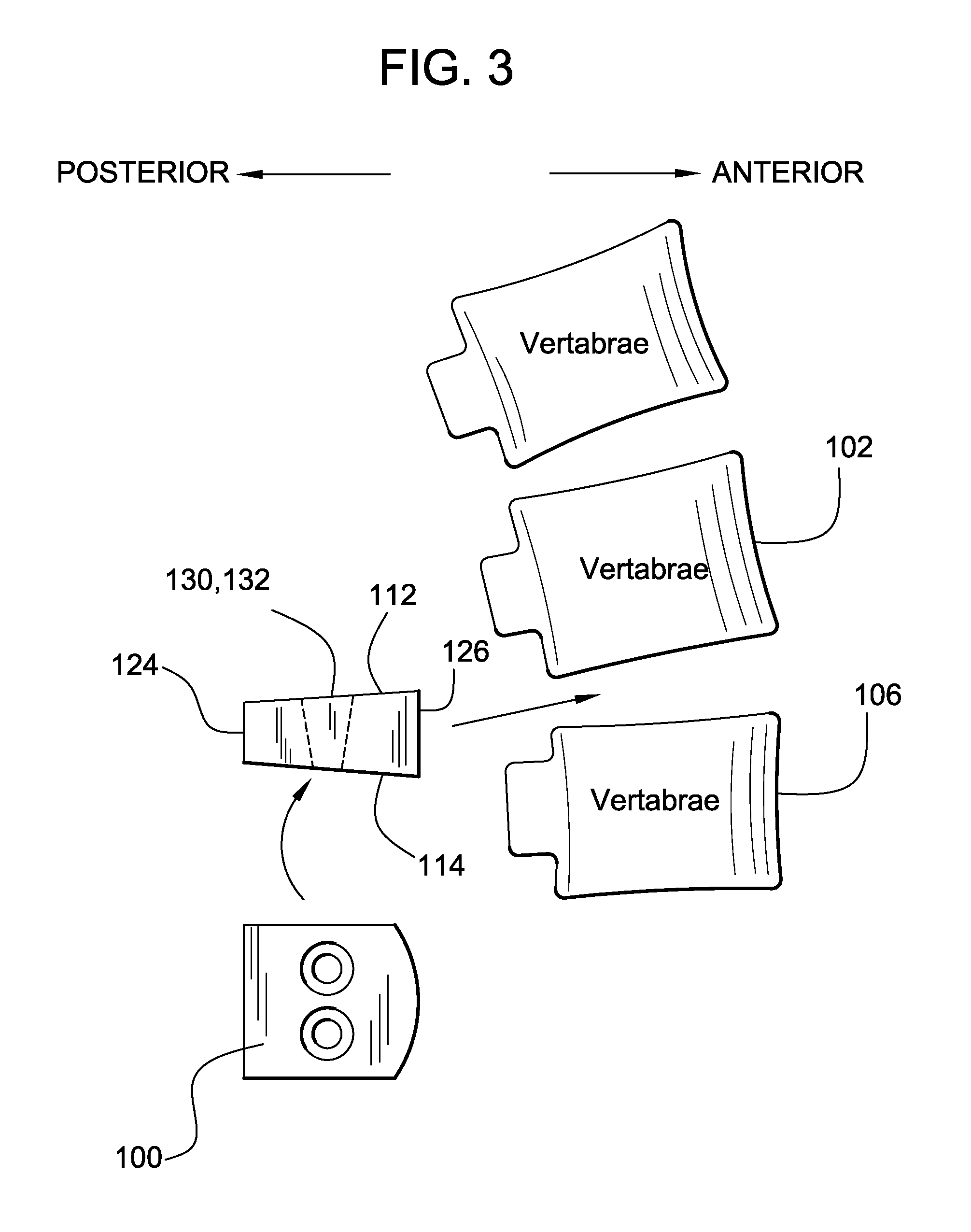
[0010]Accordingly, an advantage of the inventive intervertebral implant is that it provides strong biomechanical support to the spinal column. Another advantage is that the intervertebral implant can retain osteogenic material for promoting fusion of adjacent vertebrae. A related advantage is that the intervertebral implant can include curved grooves of a specific shape to prevent slipping of the implant from between adjacent vertebrae. Yet another advantage is that the intervertebral implant can be shaped to promote and maintain the lordotic curve of the
lumbar region in the spine. Another advantage is that inclusion of the flange on a
spinal implant facilitates grasping and manipulating the implant with
forceps. These and related advantages and features of the invention will become apparent upon review of the following drawing and

