Ceramics heat exchanger and production method thereof

a heat exchanger and ceramic technology, applied in indirect heat exchangers, machines/engines, lighting and heating apparatus, etc., can solve the problems of insufficient heat exchange between, low heat exchange efficiency, and poor structure efficiency regarding heat exchange, so as to reduce weight and cost, the effect of high heat exchange efficiency

Inactive Publication Date: 2010-10-28
NGK INSULATORS LTD
View PDF3 Cites 27 Cited by
  • Summary
  • Abstract
  • Description
  • Claims
  • Application Information

AI Technical Summary

Benefits of technology

[0023]In a ceramics heat exchanger of the present invention, attention is paid to heat and a heat exchange element which exchanges heat in exhaust heat recovery technology, and the heat exchanger realizes high heat exchange efficiency, miniaturization, weight saving, and cost reduction in comparison with a conventional heat exchange element (heat exchanger or its device).

Problems solved by technology

However, the structure does not have good efficiency regarding the heat exchange.
In addition, in the Patent Document 4, the structure is constituted of an evaporation portion (first heat exchange portion), a heat-transfer fin, and a condensation portion (second heat exchange portion) However, since it exchanges heat by means of a heat-transfer fin without directly exchanging heat, the heat exchange efficiency is low.
However, since exhaust gas flows through a gap between the flat plates, though the heat exchanger has high heat exchange efficiency in comparison with those of the Patent Documents 3 and 4, the contact area is not always large for heat transfer from the exhaust gas to the flat plates, and insufficient heat exchange may be caused between the exhaust gas and the cooling liquid.

Method used


Image

  • Ceramics heat exchanger and production method thereof
  • Ceramics heat exchanger and production method thereof
  • Ceramics heat exchanger and production method thereof

Examples


example

[0129]Hereinbelow, the present invention will be described in more detail on the basis of Examples. However, the present invention is by no means limited to these Examples.

[0130](Manufacturing of Segment of Heat Exchange Element)

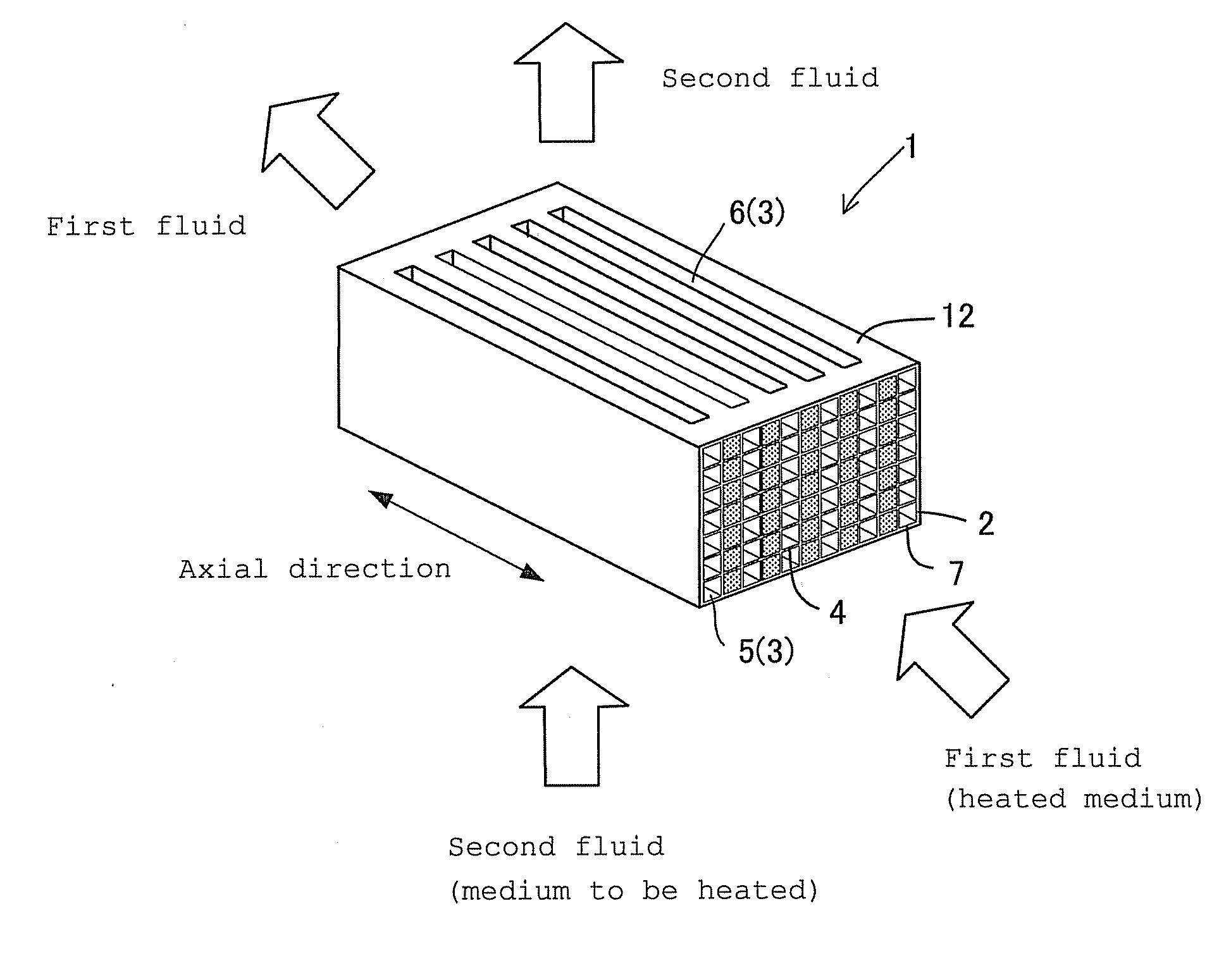
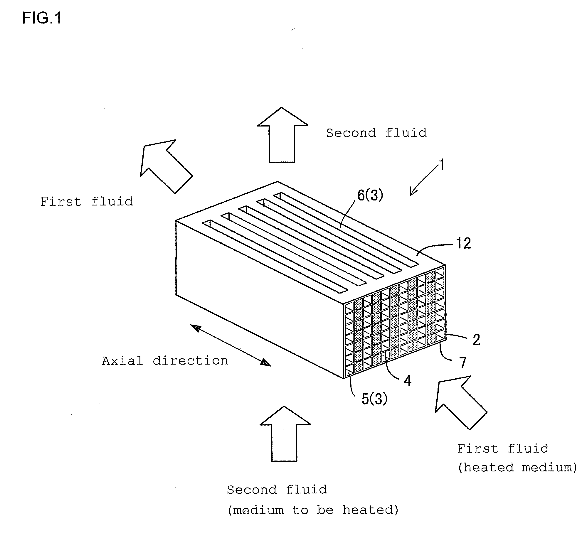
[0131]After the kneaded clay containing a ceramic powder was extruded to have a desired shape, it was dried and fired to manufacture a heat exchange element 1 of silicon carbide segment having a main body size of 33×33×60 mm.

examples 1 to 5

Comparative Examples 1 to 3

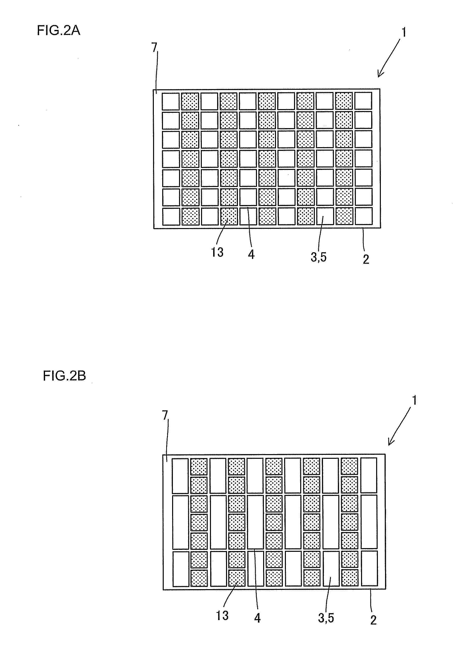
[0132]The structures of the segments of the heat exchange elements 1 of Examples 1 to 5 and Comparative Examples 1 to 3 are as in Table 1. Incidentally, no catalyst was loaded on any of the Examples and Comparative Examples. In addition, the “number of the partition walls” of the first fluid circulation portion 6 shows the number of the partition walls in one line (For example, the numbers of the partition walls are “6” in FIG. 2A and “2” in FIG. 2B.).

[0133](Heat Exchange Element-Holding Container)

[0134]As the outside container for the heat exchange element 1, a stainless steel heat exchange element-holding container 11 was used. Pipes are provided on the heat exchange element-holding container 11 in accordance with the cross-flow structure of the heat exchange element 1. Incidentally, the two routes are completely partitioned lest the first fluid and the second fluid should be mixed together.

[0135](First Fluid and Second Fluid)

[0136]The inlet temperature ...


PUM

PropertyMeasurementUnit
densityaaaaaaaaaa
thicknessaaaaaaaaaa
thicknessaaaaaaaaaa

Abstract

In a heat exchange element 1, first fluid circulation portions 5 having a honeycomb structure having a plurality of cells separated by ceramic partition walls 4, extending through in an axial direction from one end face 2 to the other end face 2, and allowing a heated medium as a first fluid to flow therethrough and second fluid circulation portions 6 being separated by ceramic partition walls 4, extending in the direction perpendicular to the axial direction, allowing a second fluid to flow therethrough, transferring heat to a medium to be heated as the second fluid are alternately formed as a unit. The cells 3 on the first fluid circulation portion 5 side are smaller than the cells 3 on the second fluid circulation portion 6 side, and the partition walls have a density of 0.5 to 5 g/cm3 and a thermal conductivity of 10 to 300 W/mK.

Description

FIELD OF THE INVENTION[0001]The present invention relates to a ceramics heat exchanger for transferring heat of the first fluid (high temperature side) to the second fluid (low temperature side).BACKGROUND OF THE INVENTION[0002]Generally, driving energy of an automobile is merely about 25% of fuel combustion energy. The rest becomes an energy loss such as a cooling loss (engine cooling water of 30%), an exhaust gas loss (exhaust gas of 30%), and the like. After 2010, in the automobile field, CO2 reduction has been becoming strict, and fuel efficiency requirements have been being tightened. Therefore, many automobile companies work on reduction of the exhaust gas loss, for example, exhaust heat recovery technology as a measure for reducing the energy loss to improve automobile gas mileage.[0003]Patent Document 1 discloses a ceramic heat exchange element where flow passages for a heated medium are disposed from one end face to the other end face of a ceramic main body and where flow p...

Claims


Application Information

Patent Timeline
Patent Type & Authority Applications(United States)
IPC IPC(8): F28D1/00B21D53/02
CPCF01N2240/02F28D7/0025Y10T29/4935F28F7/02F28F21/04F28D21/0003
Inventor TAKAHASHI, MICHIOMIZUNO, HIROSHI
Owner NGK INSULATORS LTD
Why Eureka
Try Eureka