X-ray beam device

a beam device and beam technology, applied in the direction of material analysis, material analysis using wave/particle radiation, instruments, etc., can solve the problems of limited efficiency of collimating optical systems, insufficient use of multi-layer optical elements to filter x-ray beams emitted by sources, and insufficient high-resolution diffraction applications

Active Publication Date: 2010-10-28
XENOCS
View PDF8 Cites 36 Cited by
  • Summary
  • Abstract
  • Description
  • Claims
  • Application Information

AI Technical Summary

Benefits of technology

[0007]One optical system arrangement typically used for high resolution x-ray diffraction applications is composed of an x-ray multilayer conditioning optic that is used to convert the divergent X-ray beam emitted by the X-ray source into a parallel beam before entering a crystal monochromator arranged downstream the multilayer optic. Such multilayer conditioning optic will be referred to a collimating optic in the description of the invention. The collimating effect of a multilayer conditioning optic is referring to the optical effect where a divergent beam collected by the optic is converted in a substantially parallel beam having a divergence lower than 1 milliradians typically.
[0008]FIG. 2 is illustrating a type of multilayer conditioning optic 20 producing a collimating effect wherein the optical element comprises a reflective surface being shaped according to two curvatures Cx and Cy corresponding to two different directions which are the sagittal direction (direction Y in FIG. 2) and the meridional direction (direction X in FIG. 2). These directions that will be referred to in the description of the invention can be defined with respect

Problems solved by technology

However the use of a multilayer optical element to filter the X-ray beam emitted by a source will be unsufficient for high resolution diffraction applications as for Copper X-ray beam radiation the Kα1 and Kα2 lines are merged after the reflection on the multilayer optical element.
However the efficiency of such natural crystals is limited when curved crystal elements necessary for focusing the X-ray beam emitted from the source are used (curvature deteriorates the very small lattice spacing structure).
However such collimating optical systems are limited for applications requiring a small spot dimension at the sample position (in the order of few hundred microns or less than 100 microns

Method used


Image

  • X-ray beam device
  • X-ray beam device
  • X-ray beam device

Examples


Embodiment Construction

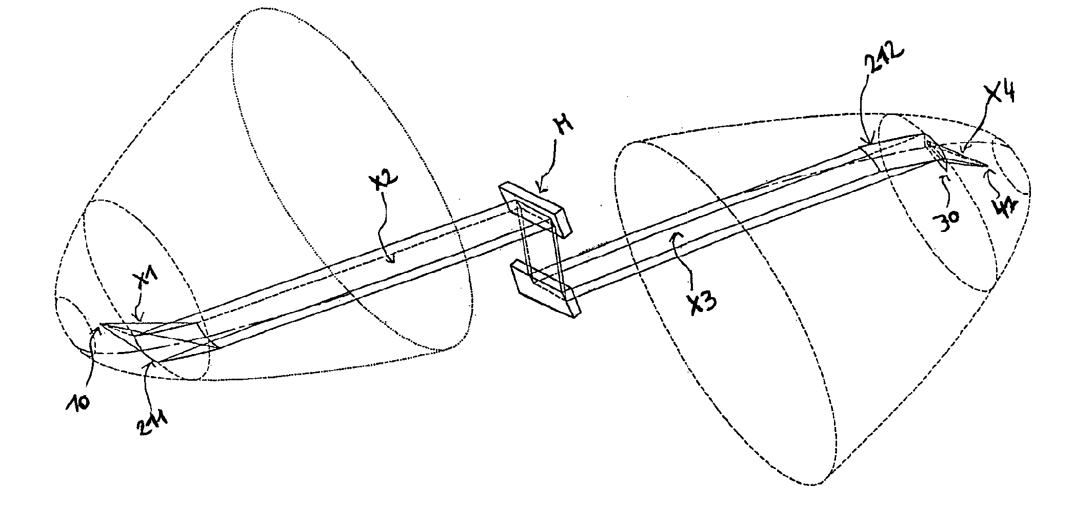
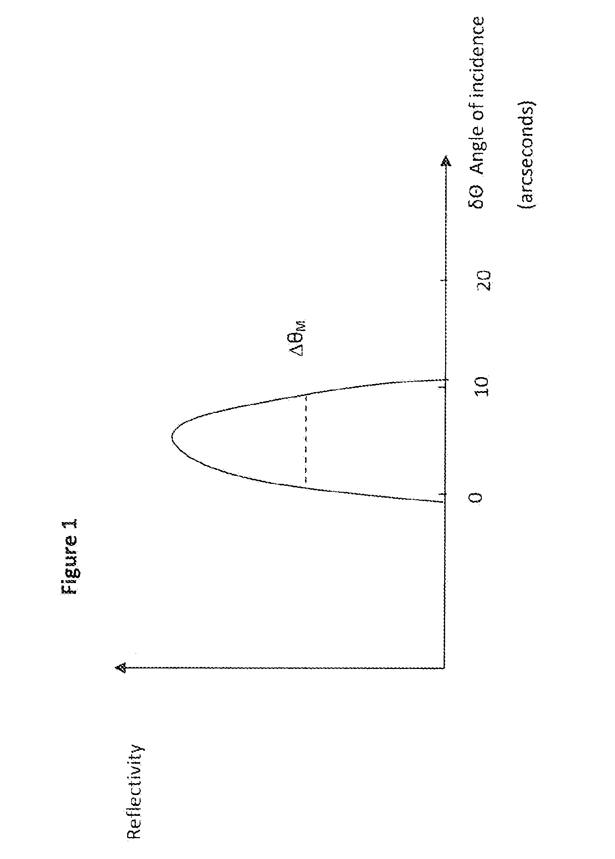
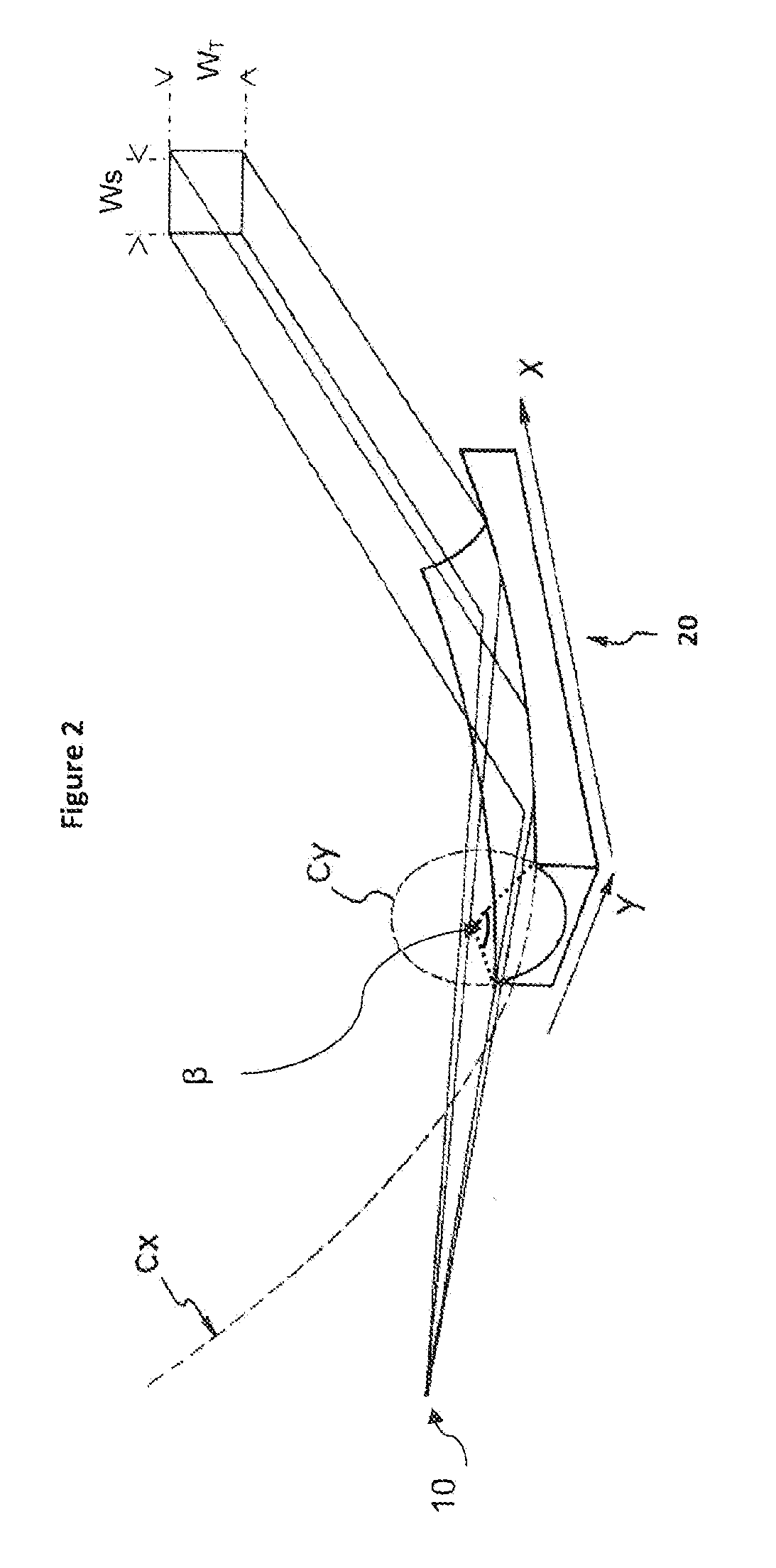
[0016]According to the invention, this object is achieved by means of an X-ray beam device for X-ray analytical applications, comprising an X-ray source designed such as to emit a divergent beam of X-rays; and an optical assembly designed such as to focus said beam onto a focal spot, wherein said optical assembly comprises a first reflecting optical element, a monochromator device and a second reflecting optical element sequentially arranged between said source and said focal spot, wherein said first optical element is designed such as to collimate said beam in two dimensions towards said monochromator device, and wherein said second optical element is designed such as to focus the beam coming from said monochromator device in two dimensions onto said focal spot.

[0017]The sample to be analyzed by means of x-ray metrology, diffraction or reflectometry can usually be located at the focal spot. Thus, the first reflecting optical element collects the divergent beam emitted by the x-ray ...


PUM


Abstract

The invention refers to an X-ray beam device for X-ray analytical applications, comprising an X-ray source designed such as to emit a divergent beam of X-rays; and an optical assembly designed such as to focus said beam onto a focal spot, wherein said optical assembly comprises a first reflecting optical element, a monochromator device and a second reflecting optical element sequentially arranged between said source and said focal spot, wherein said first optical element is designed such as to collimate said beam in two dimensions towards said monochromator device, and wherein said second optical element is designed such as to focus the beam coming from said monochromator device in two dimensions onto said focal spot.

Description

BACKGROUND AND SUMMARY[0001]The present invention relates to an X-ray beam device for X-ray analytical applications such as X-ray Diffractometry, High Resolution X-Ray Diffractometry, X-ray Reflectometry comprising an X-ray Source, typically a point focus X-ray source, and an x-ray focusing optical assembly for focusing monochromatic x-rays on a sample.[0002]The invention will be more particularly adapted for High Resolution X-ray Diffraction applications. High Resolution X-ray Diffraction is a well established technique for carrying out the analysis of high quality thin layer of near perfect single crystals materials.[0003]High resolution diffraction analysis requires to illuminate the sample with an X-ray beam having a very small divergence and a high energetic resolution. This is necessary to determine the parameters such as lattice spacing with a sufficient precision. Typically for High Resolution X-ray Diffraction applications in the case where Copper radiation is used, the ene...

Claims


Application Information

Patent Timeline
IPC IPC(8): G21K1/06G01N23/20
CPCG21K2201/062G01N23/20008
Inventor LANTZ, BLANDINEHOGHOJ, PETER
Owner XENOCS
Why Eureka
Try Eureka