Casper pin apparatus and method of use

a technology of casper pins and pins, which is applied in the field of casper pin apparatuses and methods of use, can solve the problems of large amount of blood difficult to properly size the plate length, and bleeding from the holes formed in the vertebrae, so as to achieve easy determination, no wasted time, and easy to find the proper insertion hole

Inactive Publication Date: 2010-10-28
SCHIFF DAVID C M
View PDF14 Cites 20 Cited by
  • Summary
  • Abstract
  • Description
  • Claims
  • Application Information

AI Technical Summary

Benefits of technology

[0007]The single length Casper pins are also different than the prior art Casper pins. Rather than having a wide diameter nut secured to the front portion of the pin, the front of the inventive Casper pin has a uniform outer diameter. The back ends of the inventive Casper pins have a driving surface that engages a corresponding driving surface in the insertion wrench that is mounted within a tubular section of the insertion wrench. The insertion wrench is designed to only insert the Casper pin a specific insertion depth which is typically 14 mm, 16 mm or 18 mm. The insertion depth for each insertion tool is the length of the Casper pin minus the distance between the front edge of the insertion tool and the front edge of the driving surface. The insertion depth of each wrench is clearly marked and the wrench shaft can be color coded, for example, green=14, orange=16, red=18 mm on an outer surface of the wrench so that the surgeon can easily determine the proper wrench during the operation.
[0008]During the neck surgery a needle is inserted into the disc and an X-ray and / or MRI are taken for localization. From the X-ray and / or the MRI measuring tool, the surgeon can estimate or determine the vertebral anteroposterior (a-p) depth to be operated upon. The pins should be inserted as deep as possible into the vertebrae to obtain maximum purchase in bone while leaving a safe distance from the posterior cortex of the vertebra so as to not penetrate the spinal cord. The deeper vertebra holes will provide greater surface area for the Casper pins to separate the vertebra and also provide more surface area for the screw threads to hold the plate in place after the surgery is completed. Based upon the measurements the surgeon may take from the MRI “Measuring Tool” that is part of the MRI program or simply and eyeball measurement taken from the X-ray, the proper Casper pin insertion depth is determined. The insertion wrench corresponding to the proper insertion depth is selected and the Casper pin is inserted into the selected insertion wrench.
[0014]The inventive apparatus and method have many advantages over the prior art. The inventive method is much more efficient because there is no wasted time. The improved Casper pins are used to determine the proper plate length and the pins remain in place when the plate is positioned against the vertebrae. The optimum screw length is also easily determined and it is much easier to find the proper insertion hole when the plate is in place against the vertebrae. There is also no need to drill, bore, or make any other holes in the vertebrae, minimizing bleeding, and maximizing visualization For these reasons, the inventive Casper pin apparatus and vertebrae surgery method are significant improvements over the prior art.

Problems solved by technology

The removal of the pins 101 will result in bleeding from the holes formed in vertebrae.
When the Casper pins are removed, there can be a significant amount of blood from the holes in the vertebra in addition to the bleeding as a result of the disc removal.
This bleeding often obscures the implant site and it can be difficult to properly size the plate length.
This diminished visibility can make it difficult to place the screws through the holes in the plate and into the proper place in the selected vertebrae.

Method used


Image

  • Casper pin apparatus and method of use
  • Casper pin apparatus and method of use
  • Casper pin apparatus and method of use

Examples


Embodiment Construction

[0033]The present invention is directed towards an improved Casper pin and special tools used to insert and remove the Casper pins from vertebrae. The tools include insertion wrenches that insert the Casper pins to specific insertion depths and a removal tool that can only be used to extract the Casper pins. The inventive insertion wrenches allows a single length pin to be inserted into a vertebra to any required insertion depth. The removal wrench only allows the Casper pin to be removed from the vertebra and may not be used to insert the Casper pins into the vertebra.

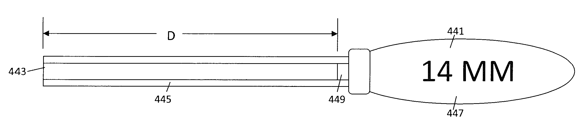
[0034]With reference to FIG. 4 the inventive Casper pin 421 includes a front tip 423, a substantially cylindrical body and a back end 431. The tip 423 may have a cutting surface 427 to assist in forming the holes and internal threads in the vertebrae. The pin 421 also has a threaded 425 outer diameter that extends from the tip 423 to the back portion 429. For example, the threads can extend from the tip 423 along the ...


PUM


Abstract

Casper pins have a single uniform length and are inserted to different depths into vertebrae using different depth insertion tools. The Casper pins have a sharp threaded tip and a drive head at the opposite end. The Casper pins are used with insertion tools that are each marked with a different insertion depth. The insertion tools each have a tubular front section and a driver within the tubular section and a handle for rotating the insertion tool. Once the proper insertion depth is determined, the Casper pin is placed into the corresponding insertion tool. Using the insertion tool, the tip of the Casper pin bores into the vertebra and when the designated insertion depth is reached, the driver of the insertion tool is separated from the driver head of the Casper pin. Thus, the Casper pin cannot be inserted beyond the designated insertion depth of the insertion tool. The process is repeated for the adjacent vertebrae so that two Casper pins extend from the patient. A distractor is used to separate the vertebrae so the surgeon can operate on the disc. Once the disc operation is completed, the distractor is removed and a plate is placed over the Casper pins and moved against the vertebrae. The Casper pins are replaced with screws to hold the plate in place against the vertebrae. With the plate in secured in place, the incision cut into the patient can be closed so the spine is allowed to heal.

Description

BACKGROUND[0001]Casper pins are typically used during neck operations such as discectomies. During the surgery, the patient's skin is incised and the spine is exposed. Before the Casper pins are inserted into the vertebra, a needle is inserted into the disc for localization of the precise vertebral level. X-rays are taken and the vertebral anteroposterior (a-p) depth, is known from the magnetic resonance imaging machine (MRI) measuring tool, or estimated to determine the proper Casper pin length for the patient. Casper pins having the selected insertion depths are placed in adjacent vertebrae on opposite sides of the damaged disc.[0002]With reference to FIG. 1, a Casper pin 101 has a tip 103, screw threads 105, a hexagonal nut 107 welded onto or formed on the pin 101 and an extension portion 109. The insertion depth D is the distance between the tip of the Casper pin and the front shoulder of the nut 107. The Casper pins come in different insertion depths including 14 mm and 16 mm. ...

Claims


Application Information

Patent Timeline
Patent Type & Authority Applications(United States)
IPC IPC(8): A61B17/86A61F5/00
CPCA61B17/7076A61B17/861A61B19/30A61B17/8875A61B17/8625A61B90/03
Inventor SCHIFF, DAVID C.M.
Owner SCHIFF DAVID C M
Why Eureka
Try Eureka