Method of welding metallic glass with crystalline metal by high-energy beam

a technology of crystalline metal and high-energy beam, which is applied in the direction of welding/soldering/cutting articles, workpiece edge portions, manufacturing tools, etc., can solve the problems of poor welding, poor workability, and metal glass, and achieve the relaxation of restrictions on welding conditions, the effect of increasing the size of the workpiece to be welded and sufficient joint strength

Active Publication Date: 2010-11-04
NAT UNIV CORP KUMAMOTO UNIV +1
View PDF4 Cites 7 Cited by
  • Summary
  • Abstract
  • Description
  • Claims
  • Application Information

AI Technical Summary

Benefits of technology

[0023]The present invention makes it possible to obtain a joined body consisting of a metallic glass and a crystalline metal, with sufficient joint strength, and promote relaxation of rest

Problems solved by technology

However, despite having such excellent properties, the metallic glass has disadvantages such as poor workability and poor weldability.
However, in cases where a welding method designed to melt a joining region is employed, a metallic glass and a crystalline metal are melt-mix

Method used


Image

  • Method of welding metallic glass with crystalline metal by high-energy beam
  • Method of welding metallic glass with crystalline metal by high-energy beam
  • Method of welding metallic glass with crystalline metal by high-energy beam

Examples


example

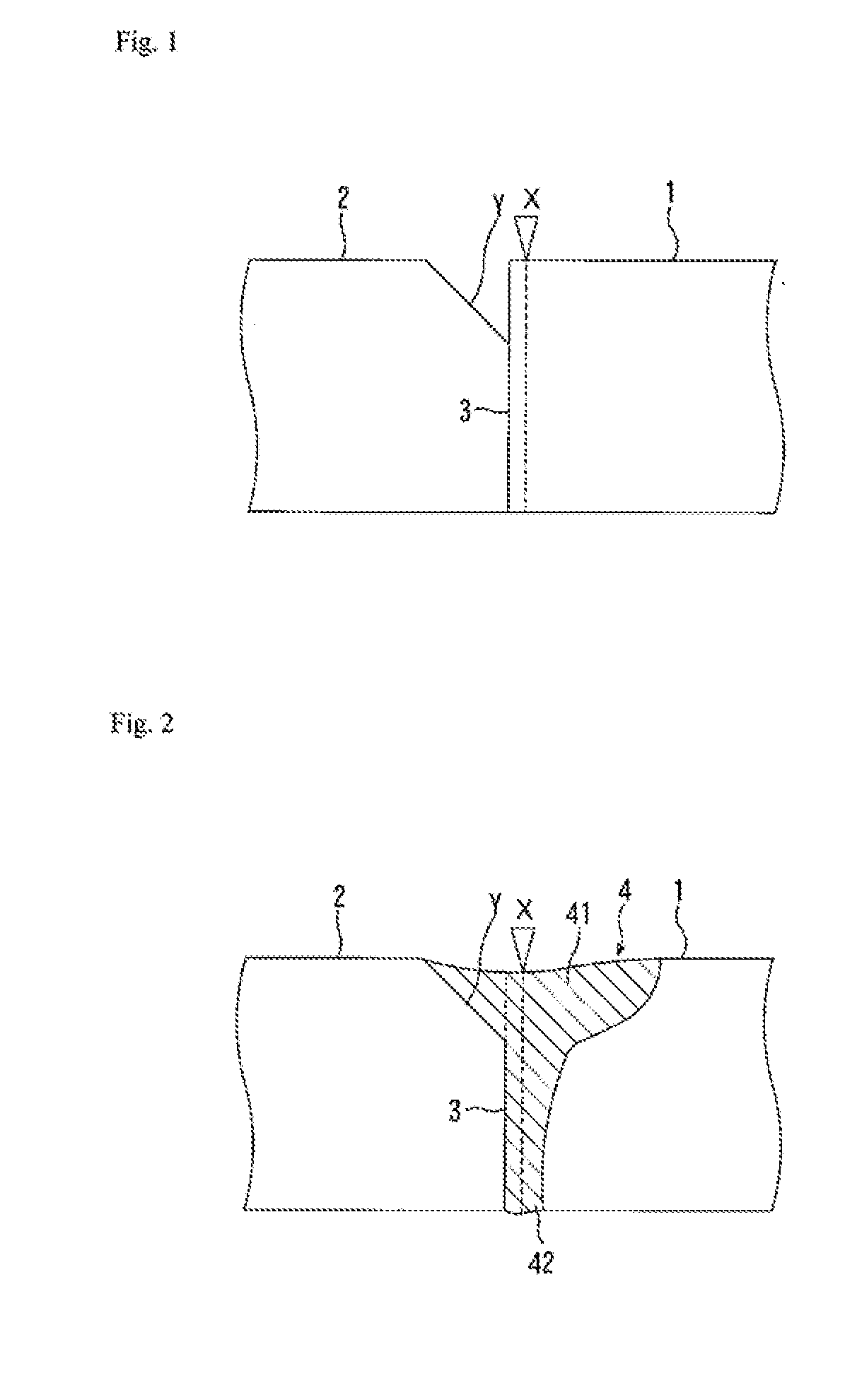
[0026]FIG. 1 shows a welding method according to the present invention. In FIG. 1, a Zr-based metallic glass was used as a metallic glass 1, and each of Zr, Ti, Ni and SUS 316L was used as a crystalline metal 2. The metallic glass 1 and the crystalline metal 2 were butted against each other to define a groove space having a depth of 0.5 mm and a width of 0.5 mm, over a linearly-cut groove Y on the side of the crystalline metal 2. A welding operation was performed under conditions that a welding current and a welding speed are verified while keeping an acceleration voltage at a constant value of 60 kV, and a welding position is shifted from a butt interface 3 toward the metal glass 1.

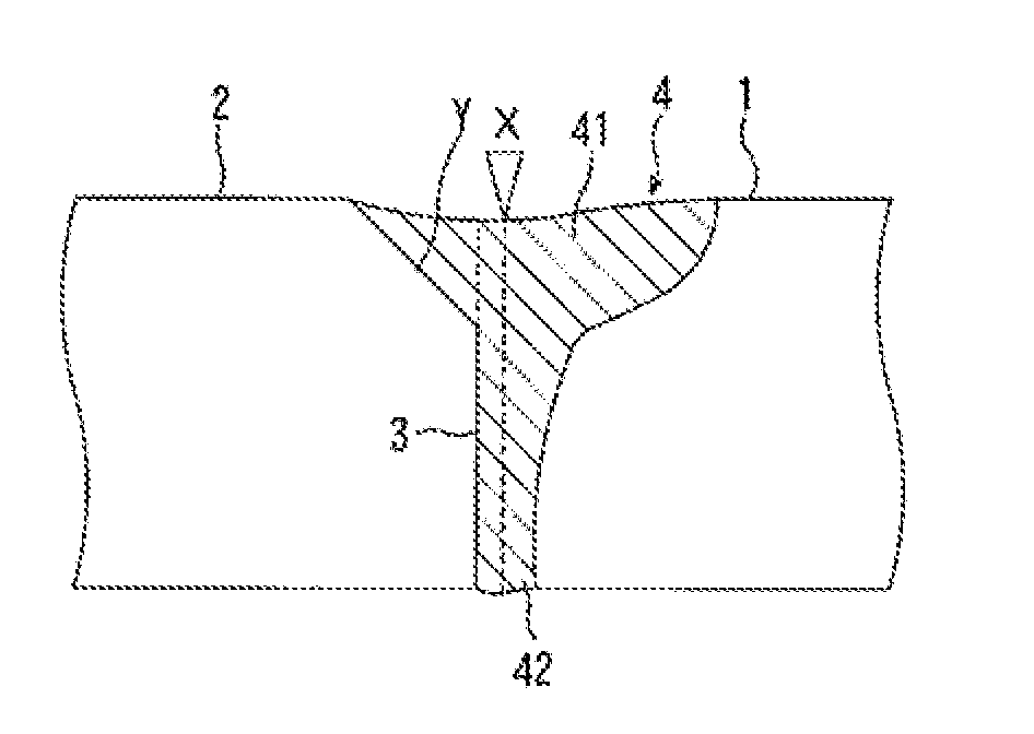
[0027]FIG. 2 shows a state after a melt of the metallic glass 1 is filled in the space defined by the groove formed on the side of the crystalline metal. As shown in FIG. 2, a melt zone 4 was formed along the butt interface 3 to have a top fused sub-region 41 with a relatively wide area including the gro...


PUM

PropertyMeasurementUnit
Angleaaaaaaaaaa
Isothermaaaaaaaaaa
Compositionaaaaaaaaaa

Abstract

[Problems] To provide a method of welding a metallic glass and a crystalline metal by shifting a high-energy beam scan area from a butting face thereof to the metallic glass side, to fall within a composition range required for glass phase formation of a metallic glass base material in a simplified assured manner.
[Means for Solving Problems] In a welding method for weldingly joining a metallic glass and a crystalline metal together by scanning a high-energy beam in a position shifted from a butt interface between the metallic glass and the crystalline metal toward the metallic glass, it is intended to provide a technique for allowing a composition of a melt zone formed around a welding interface to fall within a composition range required for forming a glass phase in the metallic glass to be joined, in a simple and more reliable manner. A metallic glass (1) and a crystalline metal (2) are butted against each other to define a groove space (Y) over a groove formed on the side of the crystalline metal (2). Then, electron beam welding is performed in a position shifted from the butt interface toward the metallic glass (1) to form a melt zone (4) which has a composition for forming an amorphous metallic glass, and comprises a top fused sub-region (41) and a lower fused sub-region (42), wherein the top fused sub-region has a relatively wide area including the groove space (Y) defined adjacent to an upper end of the butt interface and on the side of the crystalline metal, and the lower fused sub-region extends from the top fused sub-region to reach bottom surfaces of the metallic glass and the crystalline metal, while being narrowingly tapered in a downward direction.

Description

TECHNICAL FIELD[0001]The present invention relates to a method for welding an amorphous metal or a composite metal of having a crystalline phase and an amorphous phase (hereinafter referred to collectively as “metallic glass”) and a metal having a typical crystal structure (hereinafter referred to as “crystalline metal”), by scanning of a high-energy beam such as an electron beam or a laser beam.BACKGROUND ART[0002]A metallic glass is excellent in such properties as strength, hardness, wear resistance and corrosion resistance. Therefore, it is expected to be used in various fields.[0003]However, despite having such excellent properties, the metallic glass has disadvantages such as poor workability and poor weldability. Thus, in order to expanding the field of application of a metallic glass, it is important to establish a technique of welding between two metallic glasses. Furthermore, in view of fabricating an actual device component or the like, it is also necessary to establish a ...

Claims


Application Information

Patent Timeline
IPC IPC(8): C03C27/02
CPCB23K15/0093B23K26/3206B23K26/322B23K2203/18B23K33/004B23K2203/16B23K26/328B23K26/32B23K2103/05B23K2103/08B23K2103/14B23K2103/18B23K2103/26B23K2103/50
Inventor KAWAMURA, YOSHIHITOKIM, JONGHYUNKUROKI, HIRONORIYANAGIDA, YUJISAWAI, NAOHISA
Owner NAT UNIV CORP KUMAMOTO UNIV
Why Eureka
Try Eureka