
System and method for sealing sump covers

a technology of containment sumps and system components, which is applied in the directions of mechanical equipment, transportation and packaging, building repairs, etc., can solve the problems of affecting the environment, affecting the sealing effect of the containment sumps, and affecting the sealing effect of the sumps,

Active Publication Date: 2010-11-04
ROSS TIMOTHY
View PDF7 Cites 9 Cited by
  • Summary
  • Abstract
  • Description
  • Claims
  • Application Information

AI Technical Summary

Benefits of technology

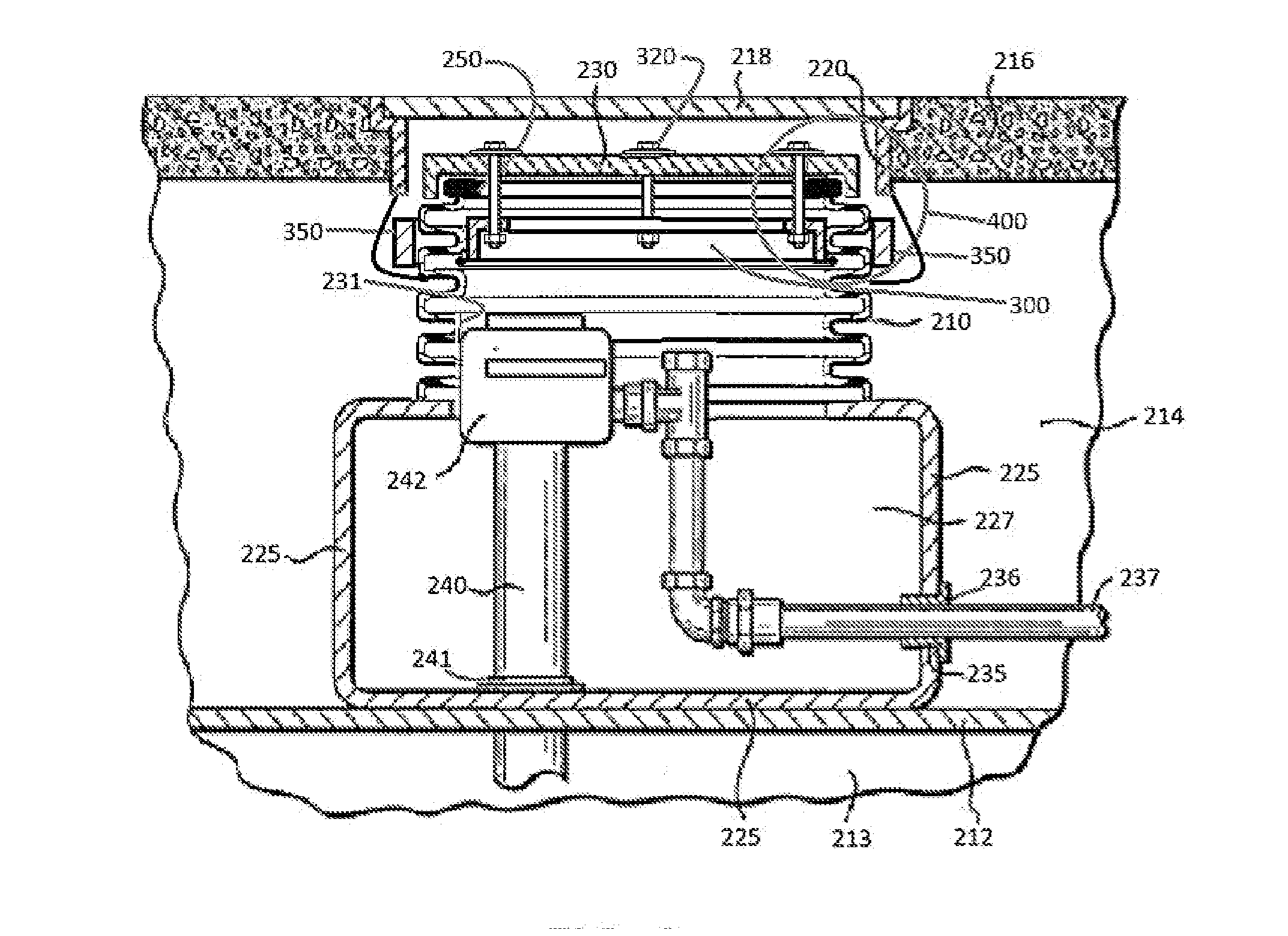
[0028]The cover may include an observation portal that allows a user outside the sump to see through the observation portal into the interior of the sump when the cover is covering the opening.

Problems solved by technology

The stored materials are often harmful to the environment.
Examples of such materials include gasoline and other petroleum products, e.g., oil and waste oil, as well as toxic raw materials and waste from manufacturing processes.
However, steel and other metal alloys are subject to rust and corrosion.
In the worst case, the hole in which the tank is installed may fill, either due to altered surface circumstances like flooding, leading to an accumulation of water in the hole, or commonly, due to a high water table.
Under these circumstances, highly corrosive brine may be present also in the hole, as is commonly encountered in coastal sites.
Corrosion of the tanks can lead to spot holing, as well as weakened strength, buckling and the like.
Whether due to holing or a structural collapse, escape of the contained materials from the confines of the tank due to a failure pose severe environmental hazards.
Cleanup of released fuel from a failed tank poses severe time and monetary considerations.
Recent, repeated severe flooding of many parts of the country has resulted in numerous underground storage tanks where the water level has risen over the top of the sump (indeed, above preexisting ground level) for an extended period of time.
Under these circumstances, where there is a sump cover (which must be removable to provide access), the sump cover may be lifted by the water and accumulated liquids pour into the sump, frustrating alarm systems, impeding access to the manway, and providing a potential threat to the integrity of dual containment in a double-walled system.
The water / silt build-up may also damage the cover or lid assembly and other components of the sump, making any initial water tight capability obsolete, and thus allowing debris, silt, or water to infiltrate the sump, thus damaging components in the sump and increasing the probability of the water, silt, and debris infiltrating the underground storage tank.
Further, when the sump is not water tight it can flood, introducing contaminants to the area outside of the sump, which is often a release point to the environment (soil, groundwater).
Spillage of even the smallest amounts build-up over the lifetime of the underground storage tank system and create certain far-reaching environmental problems.
While some attempts have been made to design new systems to prevent water infiltration into UST containment sumps, these systems have various drawbacks, some of which are discussed below, and are not adapted to inexpensively remedy the hundreds of thousands of existing UST's that presently have conventional non-water-tight containment sumps.
The system disclosed in the '361 patent would not prevent flooding of the tank in the event of flooding and / or water / silt build-up.
In practice this system would be expensive and failure prone.
For instance, typically cast iron manhole covers and receptacles would have to be precisely machined to accept a very large and expensive rubber o-ring, which is placed in an orientation and location that would cause it to readily fail in use due to abrasion, wear and tear, and degradation by water / silt sitting right against the sealing surface.
The system disclosed in the '036 patent would not prevent flooding of the tank in the event of flooding and / or water / silt build-up.
The system disclosed in the '440 and '443 patents would not prevent flooding of the tank in the event of flooding and / or water / silt build-up.
While sealing the bottom of the secondary chamber is discussed in the '633 patent, the disclosed system would not prevent flooding of either chamber in the event of flooding and / or water / silt build-up.
The '832 patent thus provides one way to attempt to seal a sump lid, but it requires a specially-designed sump container, as well as a very complicated and expensive latching mechanism.
The system described in the '832 patent could not readily be used to retrofit existing conventional sumps.
The system disclosed in the '994 patent would not prevent flooding of the tank in the event of flooding and / or water / silt build-up.
Because the '456 patent requires a riser or sump with a horizontal top flange specially configured to mate with a radial clamp, it is not adapted to retrofit the hundreds of thousands of existing UST's that have conventional sumps, which lack this feature.
And sump replacement on a buried UST would not normally be feasible, since typical sumps are permanently attached to the UST as originally formed or by application of resinous material.
To effectuate a water-tight seal in such a manner requires significant force.
For that and other reasons, the '965 patent is not adapted to retrofit existing UST's with conventional single-walled sumps.
And sump replacement on a buried UST is not normally feasible as discussed above.

Method used


Image

  • System and method for sealing sump covers
  • System and method for sealing sump covers
  • System and method for sealing sump covers

Examples


Embodiment Construction

[0038]In the following detailed description, various specific details, such as certain geometries and materials, are recited to provide a thorough understanding of specific examples of the present invention. These examples should not be understood to limit the present invention, which is intended to be defined solely by the claims. Further, certain method steps are delineated as separate steps for ease of understanding; however, these steps should not be construed as necessarily distinct nor order-dependent in their performance, unless otherwise indicated.

[0039]1. Typical Existing Underground Storage Tank Installations

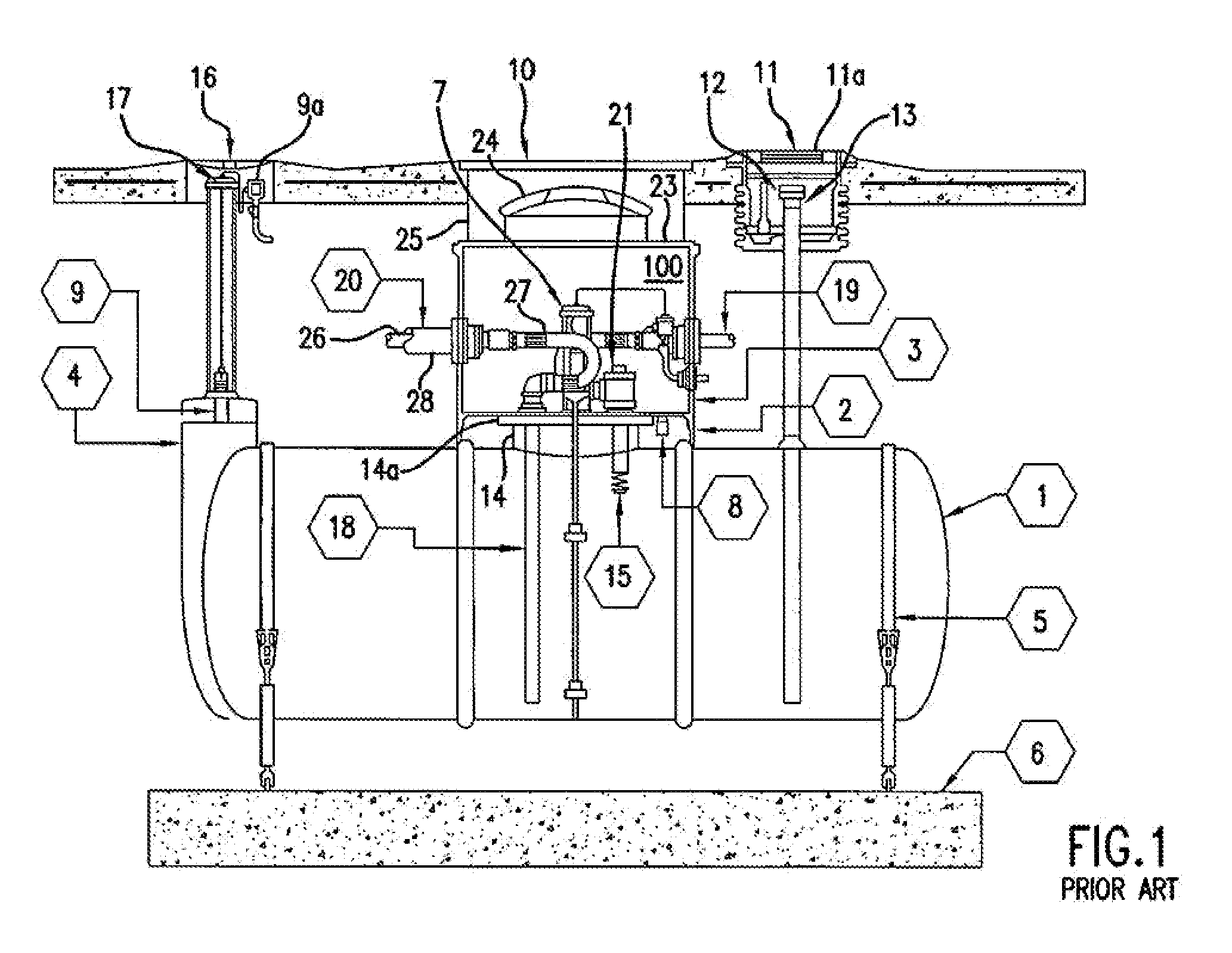
[0040]FIG. 1 illustrates a typical underground storage tank installation, in this case, a gasoline tank installation. A double walled underground storage tank (“UST”) 1 is secured by a pair of retaining straps 5 attached to a pair of deadmen 6 (one of which is visible in FIG. 1). As is well known in the art, the straps 5 and deadmen 6 are sometimes necessary to prevent...


PUM


Abstract

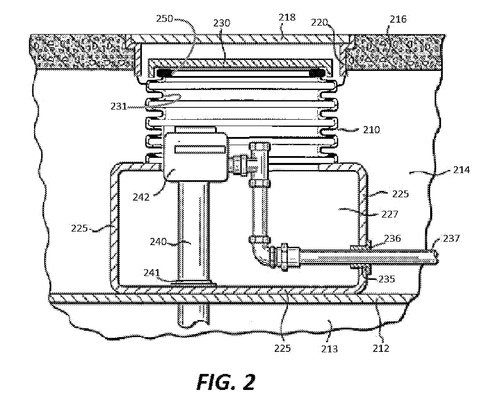
Disclosed is a system and method for sealing containment sumps used in connection with underground storage tanks. A sump cover sealing system includes an expansion ring assembly adapted to affix to the interior of the sump, and to fastenably attach with the sump cover to removably seal the sump cover to the sump. A contraction band assembly is also provided to affix to the exterior of the sump opposite the expansion ring assembly. Methods of using the system are described. A sump cover with an observation portal is provided.

Description

BACKGROUND[0001]1. Field of the Invention[0002]The invention relates to a system and method for sealing containment sumps and the like, and is suitable for use with underground storage tanks.[0003]2. Discussion of the Background[0004]Underground storage tanks (“UST”) are used in a wide variety of locations to store materials underground. The stored materials are often harmful to the environment. Examples of such materials include gasoline and other petroleum products, e.g., oil and waste oil, as well as toxic raw materials and waste from manufacturing processes. Because of the harmful nature of these materials, it is especially important to ensure that underground storage tanks containing such materials do not leak or release these materials into the environment.[0005]The use of underground storage tanks for the containment of petroleum fuels and the like is particularly well known. A typical gasoline service station installation comprises one or more underground storage tanks which...

Claims


Application Information

Patent Timeline
IPC IPC(8): B65D45/32
CPCB65D90/105
Inventor ROSS, TIMOTHY
Owner ROSS TIMOTHY
Learn More