Individual accumulator, high-pressure component, and common rail fuel injection system, as well as an internal combustion engine, electronic control unit, and method for the open-loop and/or closed-loop control of an internal combustion engine

a fuel injection system and individual accumulator technology, applied in the direction of electrical control, process and machine control, instruments, etc., can solve the problems of time lag, inaccuracy in the amount of fuel supplied to the internal combustion engine, and corruption of measurement results in the pressure sensor signal, so as to improve the accuracy

Inactive Publication Date: 2010-11-04
MOTOREN UND TURBINEN UNION MUNCHEN GMBH
View PDF13 Cites 15 Cited by
  • Summary
  • Abstract
  • Description
  • Claims
  • Application Information

AI Technical Summary

Benefits of technology

[0009]The present invention provides a device and a method of the aforementioned type, with which an individual accumulator pressure measurement can be realized that largely avoids disturbance variables in the simplest possible way and which provides improved accuracy.

Problems solved by technology

In an internal combustion engine with a common rail fuel injection system, the practical problem arises that there is a time lag between the start of energization of the injector, the needle lift of the injector, and the actual beginning of injection.
There is a corresponding problem with the end of injection.
Inaccuracy in the automatic control of the start of injection and the end of injection ultimately leads to inaccuracy in the amount of fuel supplied to the internal combustion engine.
For this purpose, it is explained that the pressure sensor should be placed as close as possible to the injection nozzle to achieve measurement results that are as exact as possible with respect to time, although it is also acknowledged that this installation site can also lead to corruption of measurements in the pressure sensor signal due to pressure fluctuations in the fuel line.
However, a problem here is that a disturbance variable characterized, for example, by the delivery frequency of a high-pressure pump and / or the injection frequency of an injector is superimposed on a measured pressure variation.
According to DE 3 118 425 C2, a characteristic for controlling the injection can be obtained from the measured pressure variation only by filtering or gradient formation, but this causes a definite time lag relative to the measured raw signal and can lead to improper corruptions of the characteristic.
Of course, in the case of the injector—as described in DE 10 2005 053 683 A1—the ratio of the inside diameter of the tube and the wall thickness is very much less favorable than in the case of the high-pressure line, so that the signal of the strain sensor to be expected at the injector is small, and the evaluation is correspondingly difficult.
In addition, the mounting of a strain sensor according to DE 10 2005 053 683 A1 on the injector itself is difficult for design reasons due to the limited installation space.

Method used


Image

  • Individual accumulator, high-pressure component, and common rail fuel injection system, as well as an internal combustion engine, electronic control unit, and method for the open-loop and/or closed-loop control of an internal combustion engine
  • Individual accumulator, high-pressure component, and common rail fuel injection system, as well as an internal combustion engine, electronic control unit, and method for the open-loop and/or closed-loop control of an internal combustion engine
  • Individual accumulator, high-pressure component, and common rail fuel injection system, as well as an internal combustion engine, electronic control unit, and method for the open-loop and/or closed-loop control of an internal combustion engine

Examples


Embodiment Construction

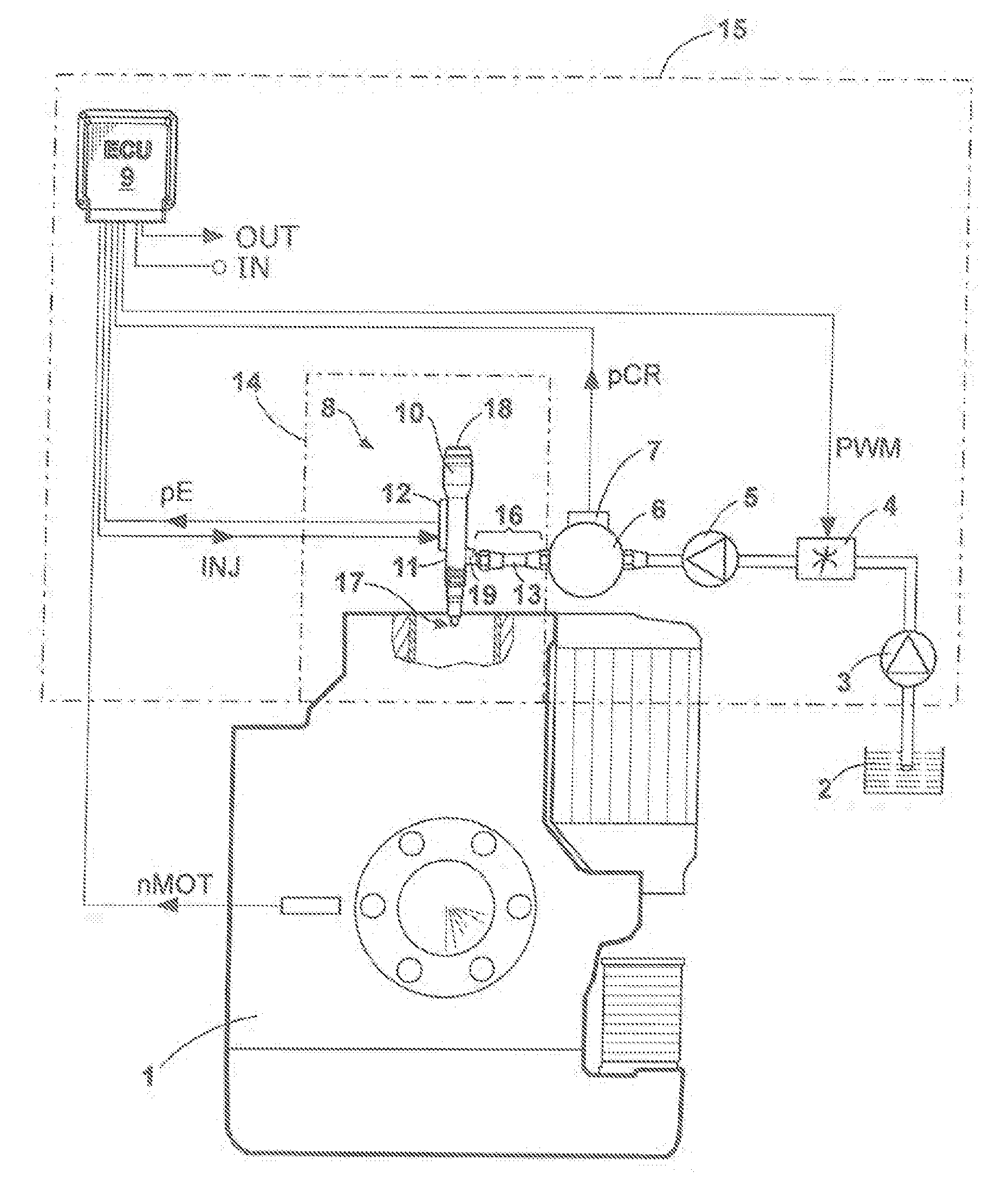
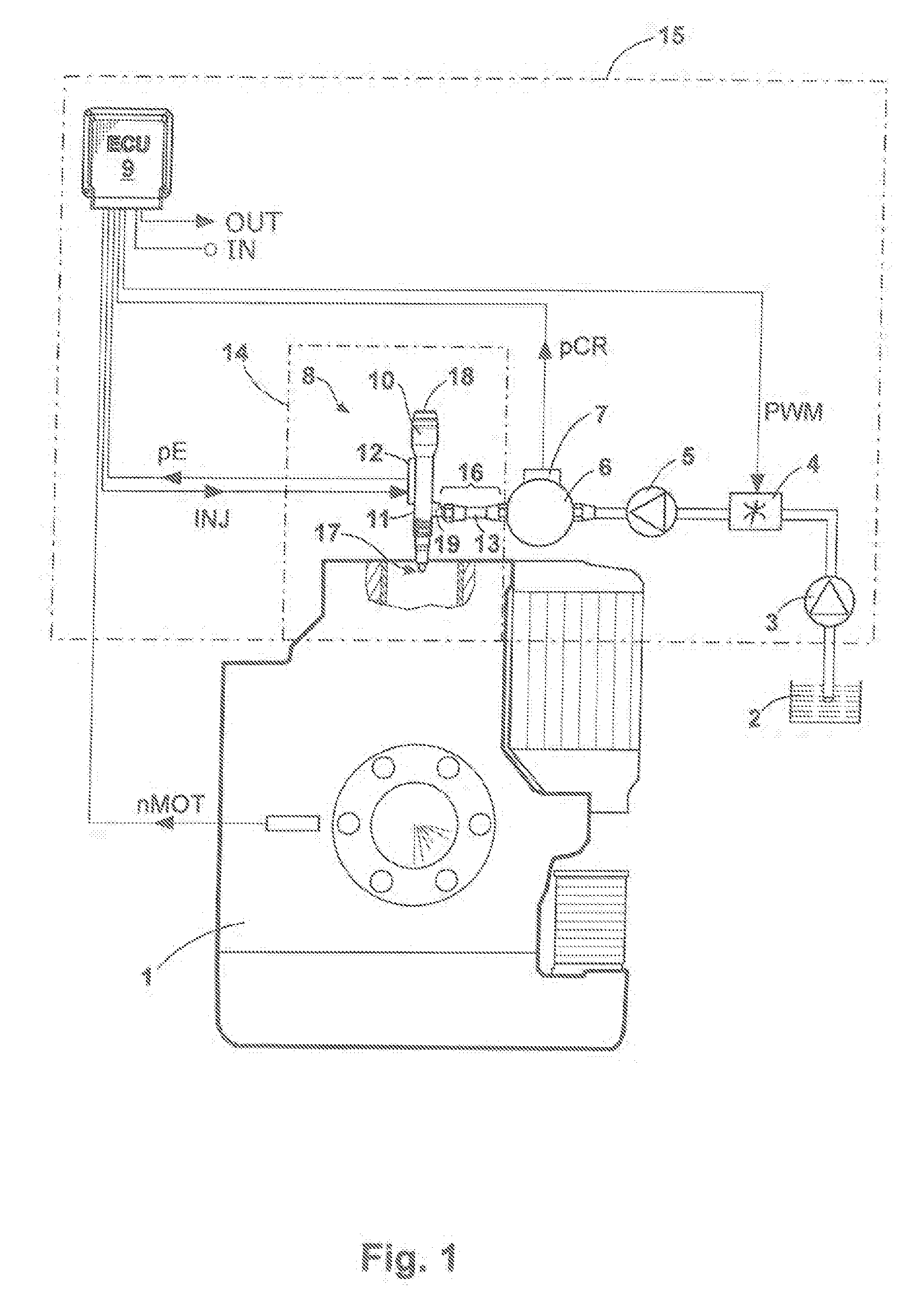
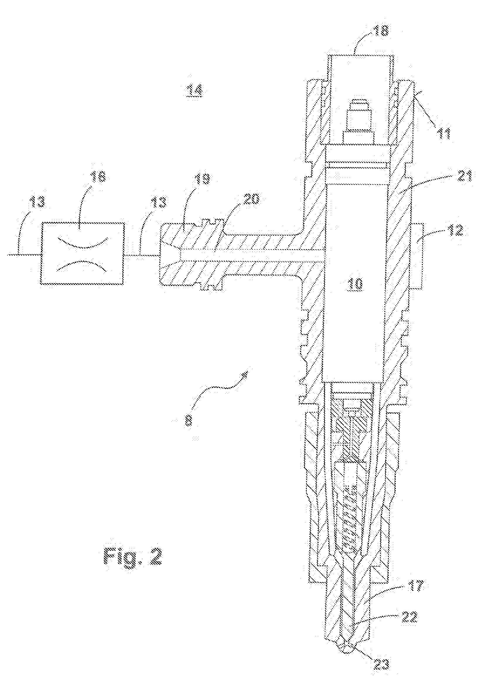
[0037]FIG. 1 shows an internal combustion engine 1 with a common rail fuel injection system 15, which is designed for injecting fuel drawn from a fuel tank 2 by a low-pressure pump 3 into a working chamber of the internal combustion engine 1. The common rail fuel injection system 15—hereinafter referred to as the common rail system 15—is provided in the present case with an electronic device 9—hereinafter referred to as the electronic control unit 9—for the open-loop and / or closed loop control of the internal combustion engine 1. Likewise in accordance with the idea of the invention, the common rail system 15 also has a high-pressure component 14 with an individual accumulator 10, which is designed for the temporary storage of the fuel before injection by the injector 8.

[0038]In detail, the common rail system 15 comprises the following mechanical components: the low-pressure pump 3 for pumping fuel from the tank 2, a suction throttle 4 for controlling the volume flow of the fuel, a ...


PUM


Abstract

An individual accumulator for a high-pressure component of a high-pressure fuel guide of a common rail fuel injection system. The individual accumulator is equipped with a pressure sensor, and the common rail fuel injection system is equipped with a source of high pressure and a fuel injector, which has a fluid connection with this source of high pressure via the high-pressure fuel guide, for injecting the fuel into a working chamber of an internal combustion engine. The pressure sensor is designed as a strain sensor.

Description

BACKGROUND OF THE INVENTION[0001]The invention concerns an individual accumulator for a high-pressure component of a high-pressure fuel guide of a common rail fuel injection system, wherein the individual accumulator is equipped with a pressure sensor, and the common rail fuel injection system is equipped with a source of high pressure and a fuel injector, which has, a fluid connection with this source of high pressure via the high-pressure fuel guide, for injecting the fuel into a working chamber of an internal combustion engine. The invention also concerns a high-pressure component of a high-pressure fuel guide of a common rail fuel injection system with an individual accumulator of this type. Furthermore, the invention concerns a common rail fuel injection system with a source of high-pressure and a fuel injector, which has a fluid connection with this source of high pressure via a high-pressure guide, for injecting the fuel into a working chamber of an internal combustion engine...

Claims


Application Information

Patent Timeline
Patent Type & Authority Applications(United States)
IPC IPC(8): F02D41/30F02M63/00F02M69/46
CPCF02D41/3845F02D41/402F02D2041/2055F02D2200/0602G01L23/24F02M63/0225F02M2200/40G01L9/0002G01L23/18F02M57/005
Inventor HEHLE, MARCGERBETH, ROBBYREMELE, JOERGSCHMIDT, GUENTHERSPEETZEN, RALFWALDER, MICHAELWILLMANN, MICHAEL
Owner MOTOREN UND TURBINEN UNION MUNCHEN GMBH
Why Eureka
Try Eureka