Laser beam welding device and method

a laser beam welding and laser beam welding technology, applied in welding equipment, metal-working equipment, manufacturing tools, etc., can solve problems such as failure of components, functional impairments, shape changes and dimensional changes,

Inactive Publication Date: 2010-11-11
ROBERT BOSCH GMBH
View PDF5 Cites 10 Cited by
  • Summary
  • Abstract
  • Description
  • Claims
  • Application Information

AI Technical Summary

Benefits of technology

[0018]Particularly good results may be achieved when the arrangement, for imaging the path of the laser focus at the circumference of the at least one workpiece, is developed as a conical mirror or a parabolic mirror, or included a conical mirror or a parabolic mirror, the conical mirror or the parabolic mirror, preferably being developed as an internal or an external mirror, depending on whether the welding seam was to be produced at the outer or the inner circumference of the workpiece. Providing a conical or parabolic-

Problems solved by technology

Because of the local thermal expansion, perhaps a microstructural transformation and the solidification of the material, an undesired delay occurs, which may lead to shape changes and dimensional changes in the component made up of the workpieces, and consequently to functional impairments, and, in the least favorable case, to failure of the component.
Cracks may form during welding, especially during the welding of dissimilar materials, i.e., different materials, based on different thermal coefficients of expansion.
This asymmetry leads to a axial runout and a deviation in dynamic balance of the component, which may be especially critical during laser welding of valve seats and may impair the sealing function of the valve.
The procedure described is not practicable for welding

Method used


Image

  • Laser beam welding device and method
  • Laser beam welding device and method
  • Laser beam welding device and method

Examples


Embodiment Construction

[0023]Identical components and components having the same function are labeled by the same reference symbols as in the figures.

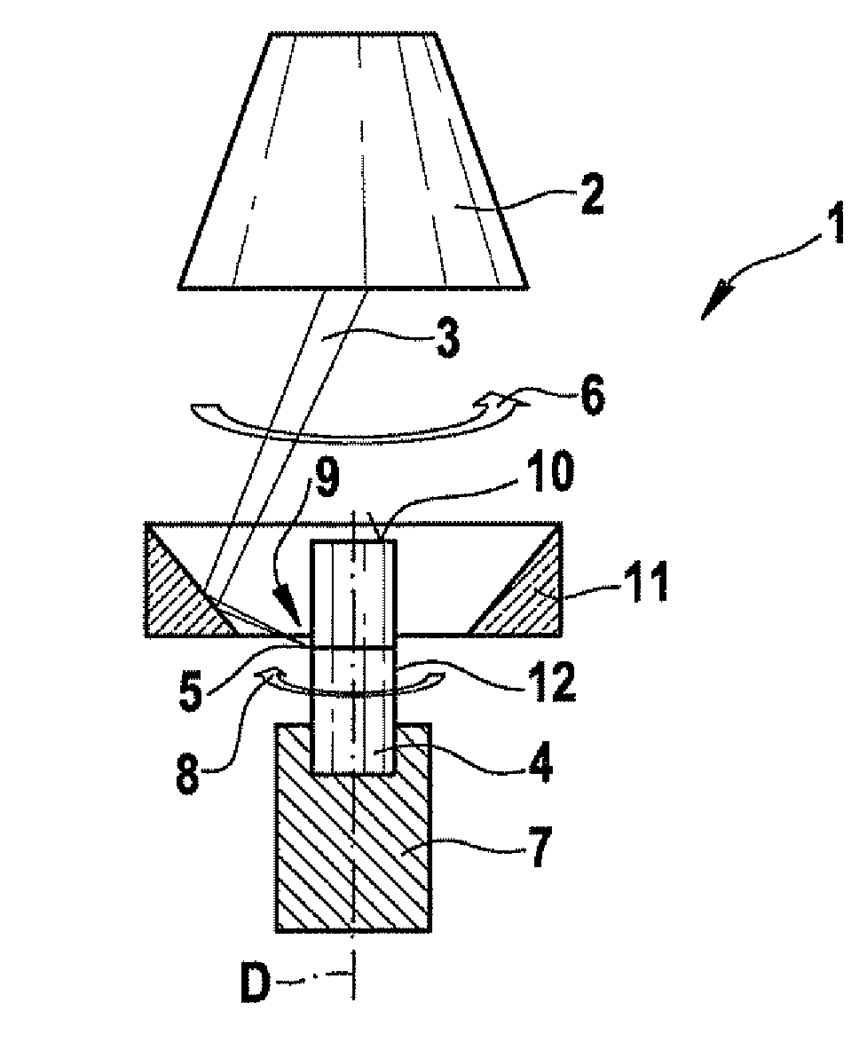
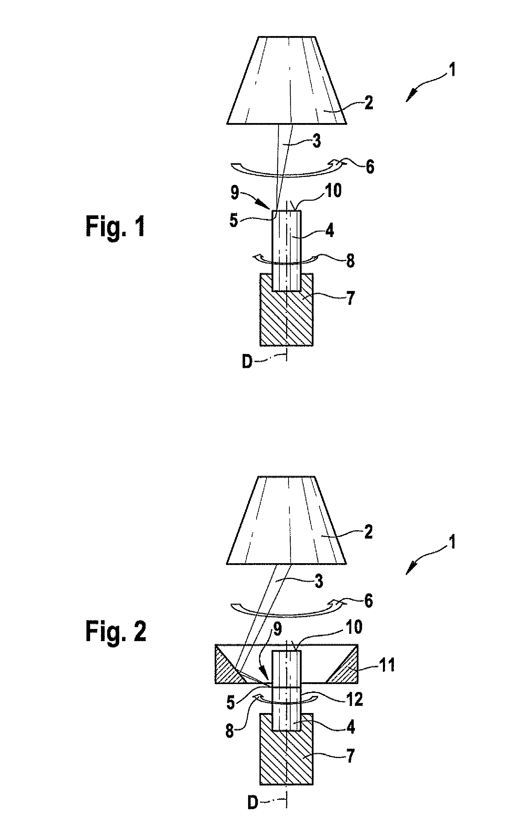
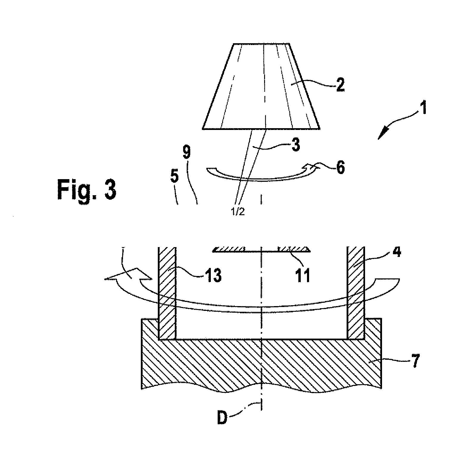
[0024]FIG. 1 shows a laser beam welding device 1. Laser beam welding device 1 includes a laser scanner 2 having a laser beam source for generating a laser beam 3 and for displacing, that is, moving laser beam 3 along a specified annular path that runs along an end face, in this exemplary embodiment, between a first workpiece 4 and a second workpiece 10 at the end face, that is developed as a cover. Using laser beam welding device 1 that is shown, an annular welding seam, lying in an end face plane, is able to be produced between workpieces 4, 10. Laser beam 3, or rather, focus 5 of laser beam 3, in this exemplary embodiment, is moved at a speed of about 60 m / min in a first direction of motion 6, in a counterclockwise direction. First workpiece 4, in common with second workpiece 10, is driven, rotationally clockwise, with the aid of driving means 7 about an a...


PUM

PropertyMeasurementUnit
Speedaaaaaaaaaa
Speedaaaaaaaaaa
Speedaaaaaaaaaa

Abstract

A laser beam welding device having a laser scanner to displace a laser beam along a specified path in a first direction of motion on at least one workpiece. A driving arrangement is provided for driving the workpieces in a second direction of motion so as to increase the relative speed between the laser beam and the workpiece. A laser beam welding method is also provided.

Description

FIELD OF THE INVENTION[0001]The present invention relates to a laser beam welding device and a laser beam welding method.BACKGROUND INFORMATION[0002]In laser beam welding, the laser beam is focused in the joining zone (weld zone) of two or more workpieces that are to be welded. The absorption of the laser beam leads to the heating and melting and often to the partial vaporization of the material. The welding connection is created by the intermixture taking place during the joining of several workpieces of the melt and the subsequent re-solidification of the material. Because of the local thermal expansion, perhaps a microstructural transformation and the solidification of the material, an undesired delay occurs, which may lead to shape changes and dimensional changes in the component made up of the workpieces, and consequently to functional impairments, and, in the least favorable case, to failure of the component. Cracks may form during welding, especially during the welding of dis...

Claims


Application Information

Patent Timeline
IPC IPC(8): B23K26/00
CPCB23K26/0884B23K26/0823
Inventor RAMSAYER, REINERKITTEL, SONJA
Owner ROBERT BOSCH GMBH
Why Eureka
Try Eureka