
Method and system for vacuum driven mass spectrometer interface with adjustable resolution and selectivity

a mass spectrometer and adjustable resolution technology, applied in the field of vacuum-driven mass spectrometer interface with adjustable resolution and selectivity, can solve the problems of reducing sensitivity and the price, and achieve the effects of increasing selectivity, reducing sensitivity, and increasing the residence time of ions

Inactive Publication Date: 2010-11-11
DH TECH DEVMENT PTE
View PDF16 Cites 46 Cited by
  • Summary
  • Abstract
  • Description
  • Claims
  • Application Information

AI Technical Summary

Benefits of technology

[0006]Typically, there is a tradeoff between selectivity and sensitivity, both of which are linked to the residence time of the ions in the differential mobility spectrometer. Specifically, increasing the residence time of the ions in the differential mobility spectrometer may increase selectivity, but at the price of reducing sensitivity.

Problems solved by technology

Specifically, increasing the residence time of the ions in the differential mobility spectrometer may increase selectivity, but at the price of reducing sensitivity.

Method used


Image

  • Method and system for vacuum driven mass spectrometer interface with adjustable resolution and selectivity
  • Method and system for vacuum driven mass spectrometer interface with adjustable resolution and selectivity
  • Method and system for vacuum driven mass spectrometer interface with adjustable resolution and selectivity

Examples


first embodiment

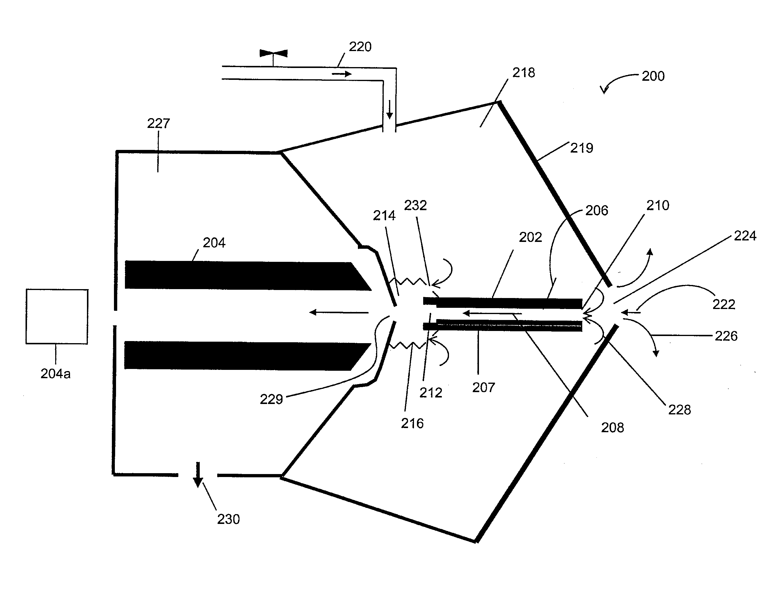
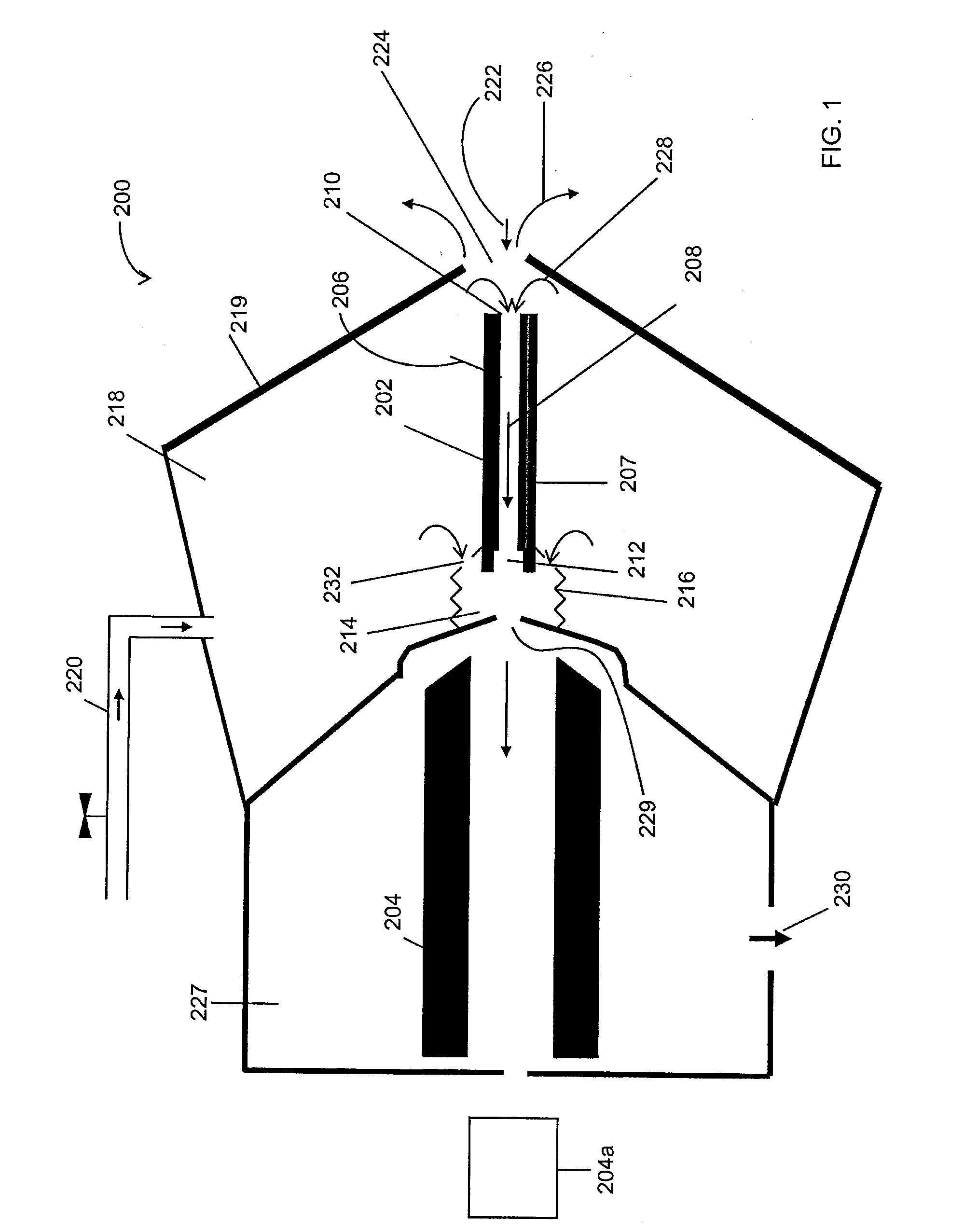
[0034]Referring to FIG. 1, there is illustrated in a schematic view, a differential mobility spectrometer / mass spectrometer system 200 in accordance with an aspect of the present invention. The differential mobility spectrometer / mass spectrometer system 200 comprises a differential mobility spectrometer 202 and a first vacuum lens element 204 of a mass spectrometer (hereinafter generally designated mass spectrometer 204). Mass spectrometer 204 also comprises mass analyzer elements 204a downstream from vacuum chamber 227. Ions can be transported through vacuum chamber 227 and may be transported through one or more additional differentially pumped vacuum stages prior to the mass analyzer indicated schematically as mass analyzer elements 204a. For instance in one embodiment, a triple quadrupole mass spectrometer may comprise three differentially pumped vacuum stages, including a first stage maintained at a pressure of approximately 2.3 Torr, a second stage maintained at a pressure of a...

second embodiment

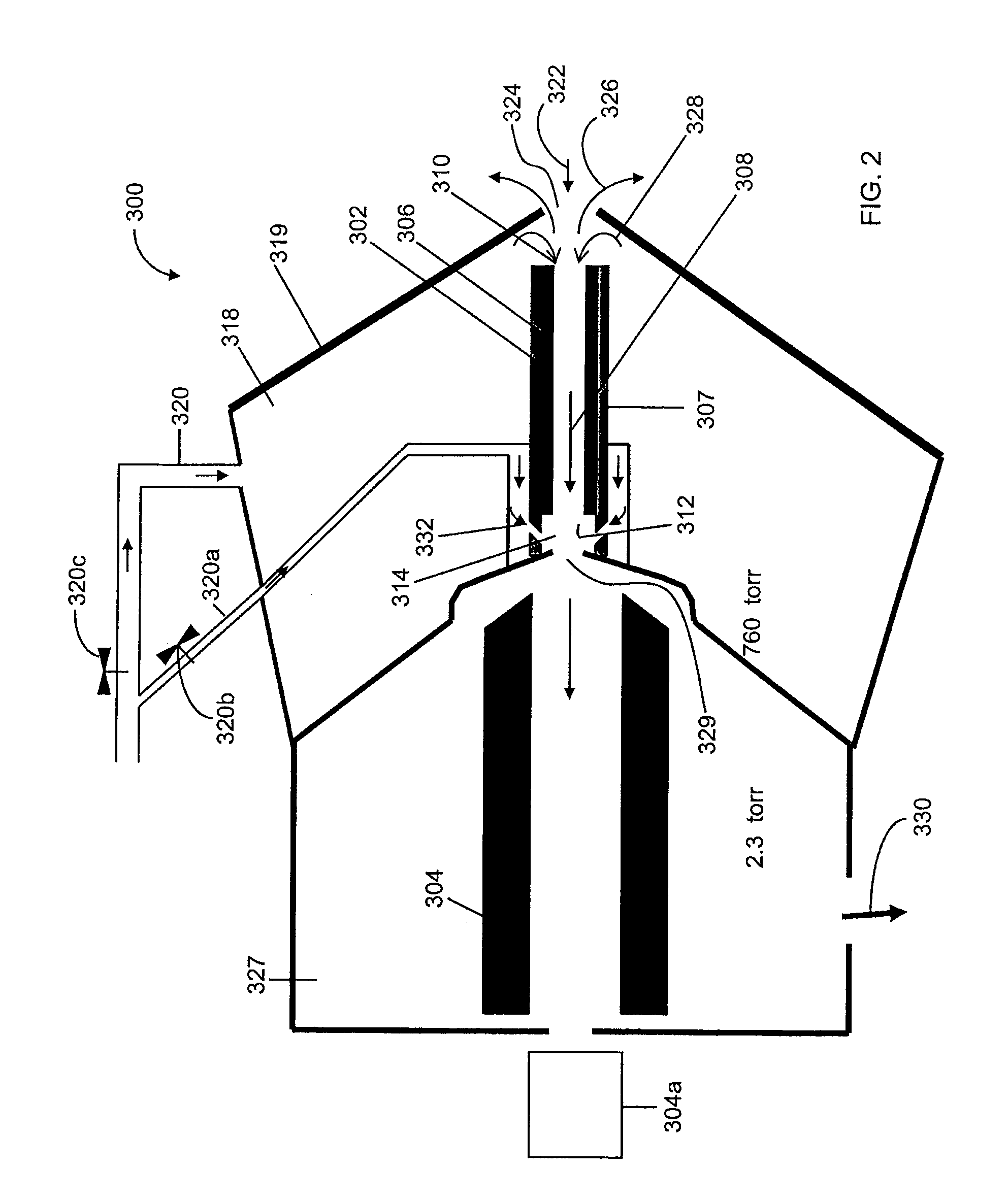
[0045]Referring to FIG. 2, there is illustrated in a schematic view, a differential mobility spectrometer / mass spectrometer system 300 in accordance with an aspect of the present invention. For clarity, the same reference numerals used in FIG. 1, with 100 added, are used in FIG. 2 to designate elements analogous to the elements of FIG. 1. For brevity, the description of FIG. 1 is not repeated with respect to FIG. 2.

[0046]It is important to note that due to the compensation voltage provided to the plates or electrodes of the differential mobility spectrometer, the actual DC potential of one or both of the electrodes of the differential mobility spectrometer may not differ by the DMS DC offset amount from the declustering potential applied to vacuum chamber inlet element. For example, say that a declustering potential is applied to vacuum chamber inlet element 329. This declustering potential (DP) is determined based on the m / z of the ion being selected by the differential mobility sp...

third embodiment

[0056]Referring to FIG. 3, there is illustrated in a schematic view, a differential mobility spectrometer / mass spectrometer system 400 in accordance with an aspect of the present invention. For clarity, the same reference numerals used in FIG. 2, with 100 added, are used in FIG. 3 to designate elements analogous to the elements of FIG. 2. For brevity, the descriptions of FIGS. 1 and 2 are not repeated with respect to FIG. 3.

[0057]As with the system 300 of FIG. 2, the resolution or selectivity of system 400 of FIG. 3 can be adjusted by adding throttle gas to a juncture chamber 414 between the differential mobility spectrometer 402 and the vacuum chamber inlet 429. As with system 300 of FIG. 2, a common source can be provided for both the curtain gas and the throttle gas.

[0058]In addition, gas restriction plates 434 are provided at an inlet 410 of the differential mobility spectrometer 402. These gas restriction plates 434 can facilitate tuning the pressure of the differential mobilit...


PUM


Abstract

A mass spectrometer system and a method of operating same are provided. The system comprises a) an ion conduit for receiving ions; b) a boundary member defining a curtain gas chamber containing the ion conduit; c) a curtain gas supply for providing a curtain gas directed by the boundary member to an inlet of the ion conduit to provide a gas flow into the ion conduit, and a curtain gas outflow out of a curtain gas chamber inlet; d) a mass spectrometer at least partially sealed to, and in fluid communication with, the ion conduit for receiving the ions from the ion conduit; a vacuum chamber surrounding the mass spectrometer operable to draw the gas flow including the ions through the ion conduit and into the vacuum chamber; and, e) a gas outlet for drawing a gas outflow from the gas flow located between the ion conduit and the mass spectrometer to increase the gas flow rate through the ion conduit.

Description

[0001]This is a continuation-in-part of U.S. application Ser. No. 12 / 473,859 filed on May 28, 2009, which in turn claims priority from U.S. provisional application No. 61 / 057,242 filed May 30, 2008 and U.S. provisional application No. 61 / 178,675 filed May 15, 2009. The contents of U.S. application Ser. Nos. 12 / 473,859, 61 / 057,242 and 61 / 178,675 are incorporated herein by reference.INTRODUCTION[0002]The present invention relates generally to methods and systems involving both a mass spectrometer and a differential mobility spectrometer.[0003]In differential mobility spectrometer / mass spectrometer systems, a drift gas is typically supplied from a compressed gas source upstream of the differential mobility spectrometer. This drift gas acts as a carrier gas flow through the differential mobility spectrometer. The delivery of the drift gas to the differential mobility spectrometer can be controlled by flow restriction valves. Sensitivity is related to the transmission efficiency of the s...

Claims


Application Information

Patent Timeline
Patent Type & Authority Applications(United States)
IPC IPC(8): H01J49/26H01J49/24H01J49/02
CPCG01N27/622H01J49/004H01J49/26H01J49/0468H01J49/24H01J49/0404G01N27/623
Inventor SCHNEIDER, BRADLEYCOVEY, THOMAS
Owner DH TECH DEVMENT PTE
Learn More