Power supply device and method for driving the same

a technology of power supply device and power supply method, which is applied in the direction of pulse generator, pulse technique, instruments, etc., can solve the problems of limiting the effect of reverse recovery loss, and the inability to effectively reduce both constant loss and reverse recovery loss. , to achieve the effect of facilitating the flow of return current, forward voltage drop, and reduced constant loss

Active Publication Date: 2010-11-11
DENSO CORP
View PDF14 Cites 16 Cited by
  • Summary
  • Abstract
  • Description
  • Claims
  • Application Information

AI Technical Summary

Benefits of technology

[0100]As has been described above, according to the present teachings, the characteristics of the return diode can be actively controlled. When the return current flows to the return diode, the forward voltage drop can be lowered and the constant loss can be reduced by increasing the quantity of minority carriers and switching to a state that facilitates the flow of the return current. In addition, when the reverse recovery current flows to the return diode, increase in the reverse recovery current can be inhibited by either preliminarily reducing the quantity of the minority carriers that increase the reverse recovery current, or by inhibiting the migration of the minority carriers that otherwise would increase the reverse recovery current if no restrictions are placed on the minority carriers. Electric power loss attributable to the reverse recovery operation can be reduced.
[0101]Wasteful consumption of electric power by the power supply device can be reduced by adjusting the quantity of the minority carriers according to the state of the return diode.

Problems solved by technology

Although the technology that uses lifetime control is an effective technology, there are limits on its effect.
The reverse recovery loss thus can no longer be reduced.
There are limitations on effectively reducing both the constant loss and the reverse recovery loss by providing a low lifetime layer.
Furthermore, in the case of configuring a power supply device using reverse conducting semiconductor devices in each of which the IGBT domain and the diode element domain coexist in the same semiconductor substrate, it is difficult to form the low lifetime layer by selecting the diode element domain.
In addition, even in the case of configuring a power supply device using the reverse conducting semiconductor devices, there are limitations on effectively reducing both the constant loss and the reverse recovery loss.

Method used


Image

  • Power supply device and method for driving the same
  • Power supply device and method for driving the same
  • Power supply device and method for driving the same

Examples


Embodiment Construction

Preferred Features of an Embodiment of the Invention

[0144]Some of the features of the below-described embodiment will be listed.

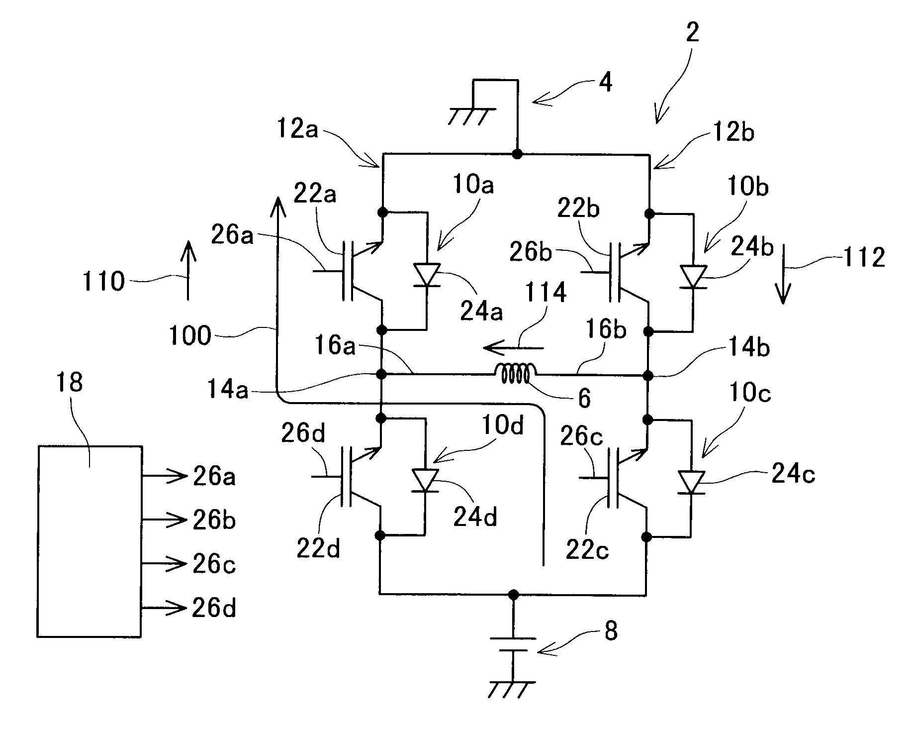
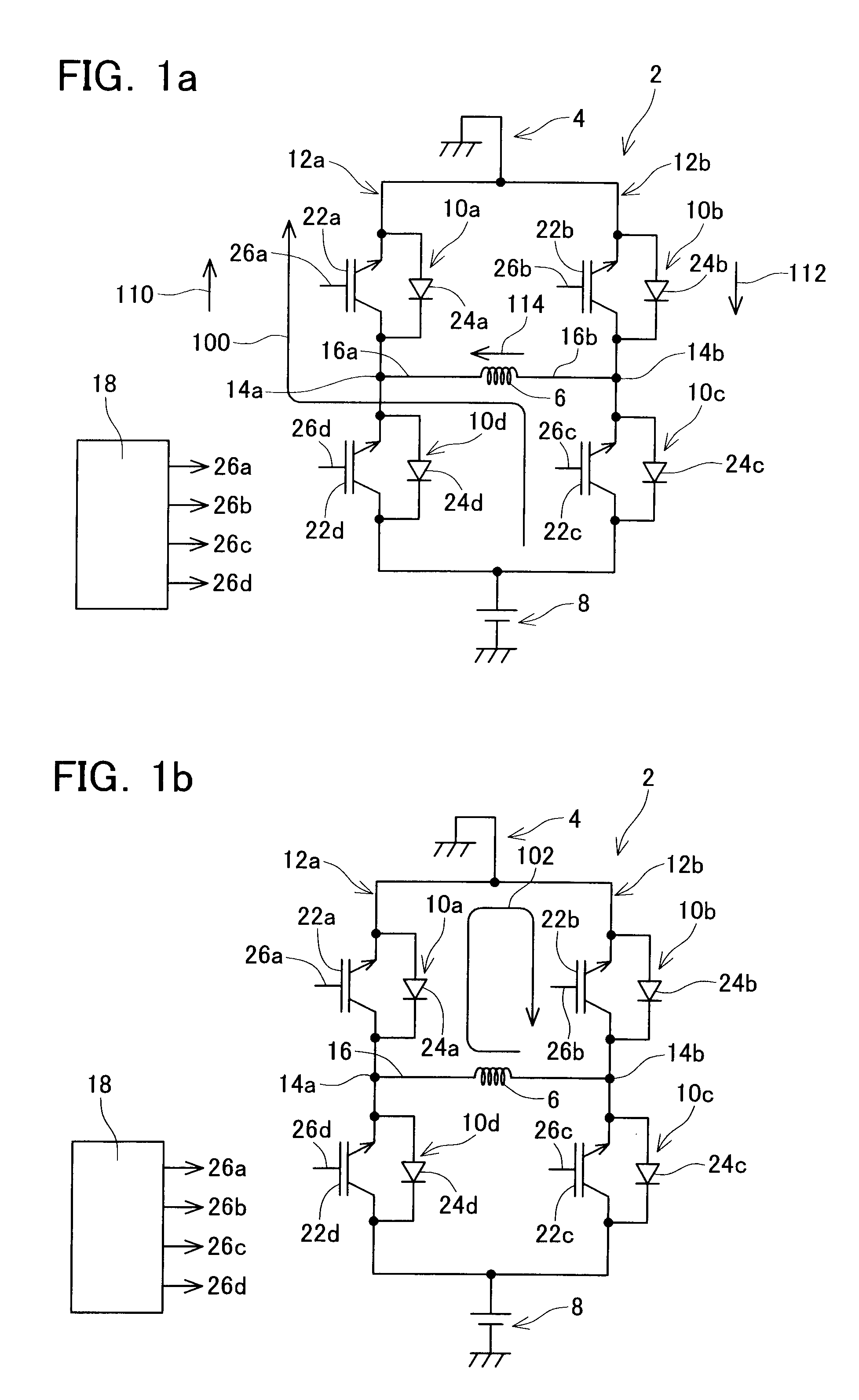
[0145](Feature 1) The power supply device that is driven by the driving method of the present teachings is an inverter circuit.

[0146](Feature 2) The power supply of the present teachings is provided with a plurality of reverse conducting semiconductor devices. The each of reverse conducting semiconductor devices is provided with an IGBT domain provided with a trench gate electrode, and a diode element domain provided with a trench gate electrode. The trench gate electrode of the IGBT domain and the trench gate electrode of the diode element domain are connected to the same gate voltage control circuit and are adjusted to the same electric potential.

[0147](Feature 3) At least one of an emitter electrode and a collector electrode of the reverse conducting semiconductor devices are divided into two electrodes, and one of the divided electrodes is connected to ...


PUM


Abstract

In a reverse conducting semiconductor device, which forms a composition circuit, a positive voltage that is higher than a positive voltage of a collector electrode may be applied to an emitter electrode. In this case, in a region of the reverse conducting semiconductor device in which a return diode is formed, a body contact region functions as an anode, a drift contact region functions as a cathode, and current flows from the anode to the cathode. When a voltage having a lower electric potential than the collector electrode is applied to the trench gate electrode at that time, p-type carriers are generated within the cathode and a quantity of carriers increases within the return diode. As a result, a forward voltage drop of the return diode lowers, and constant loss of electric power can be reduced. Electric power loss can be reduced in a power supply device that uses such a composition circuit in which a switching element and the return diode are connected in reverse parallel.

Description

CROSS-REFERENCE TO RELATED APPLICATION[0001]This application claims priority to Japanese Patent Application No. 2007-234063, filed on Sep. 10, 2007, the contents of which are hereby incorporated by reference into the present application.BACKGROUND OF THE INVENTION[0002]1. Field of the Invention[0003]The present invention relates to a power supply device that supplies power to an electrical load such as a motor, and a method for driving the same.[0004]2. Description of the Related Art[0005](Explanation of a Power Supply Device for which the Present Invention is Useful)[0006]A known example of a power supply device is shown in FIGS. 8A to 8F. A power supply device 80 of FIG. 8A is a device for supplying power to a motor M. The power supply device 80 is provided with a series circuit A in which two switching elements A1 and A2 are connected in series and a series circuit B in which two switching elements B1 and B2 are connected in series. The series circuits A and B are connected in pa...

Claims


Application Information

Patent Timeline
Patent Type & Authority Applications(United States)
IPC IPC(8): G05F3/02
CPCH01L29/0834H03K17/0828H03K17/08128H01L29/7397
Inventor SOENO, AKITAKASAITO, JUNAMARATUNGA, GEHAN ANIL JOSEPHUDREA, FLORIN
Owner DENSO CORP
Why Eureka
Try Eureka