Moving high flux x-ray target and assembly

a high-fluid, x-ray tube technology, applied in the direction of x-ray tube electrodes, electrical devices, electric discharge tubes, etc., can solve the problems of deterioration and breakdown of the target structure, relatively low life, and inability to move, so as to improve heat management, increase dissipation, and improve heat dissipation.

Inactive Publication Date: 2010-11-11
GENERAL ELECTRIC CO
View PDF2 Cites 2 Cited by
  • Summary
  • Abstract
  • Description
  • Claims
  • Application Information

AI Technical Summary

Benefits of technology

[0010]The position of the focal point along the surface of the target is varied, providing improved heat management, wherein the heat may be dissipated more easily. In addition, the increased dissipation permits the use of higher power and longer durations than are available with the use of a stationary anode arrangement. In addition, the anode has increased life over anodes that have a fixed focal point on the anode. The anode target motion provides longer life than solid lubricated bearings used in known rotating anode sources.
[0011]Another advantage of the present disclosure includes the reduction or elimination in dwell or delay time for anode motion reducing or eliminating heat build up due to reversal of...

Problems solved by technology

In addition, the high velocity beam of electrons impinging the target surface generates extremely high and localized temperatures in the target structure accompanied by high internal stresses leading to deterioration and breakdown of the target structure.
Heating remains a major problem in X-ray anode target structures.
Traditional x-ray target bearings are solid lubricated, which have relatively low life.
Stationary targets do not have this ...

Method used


Image

  • Moving high flux x-ray target and assembly
  • Moving high flux x-ray target and assembly
  • Moving high flux x-ray target and assembly

Examples


Embodiment Construction

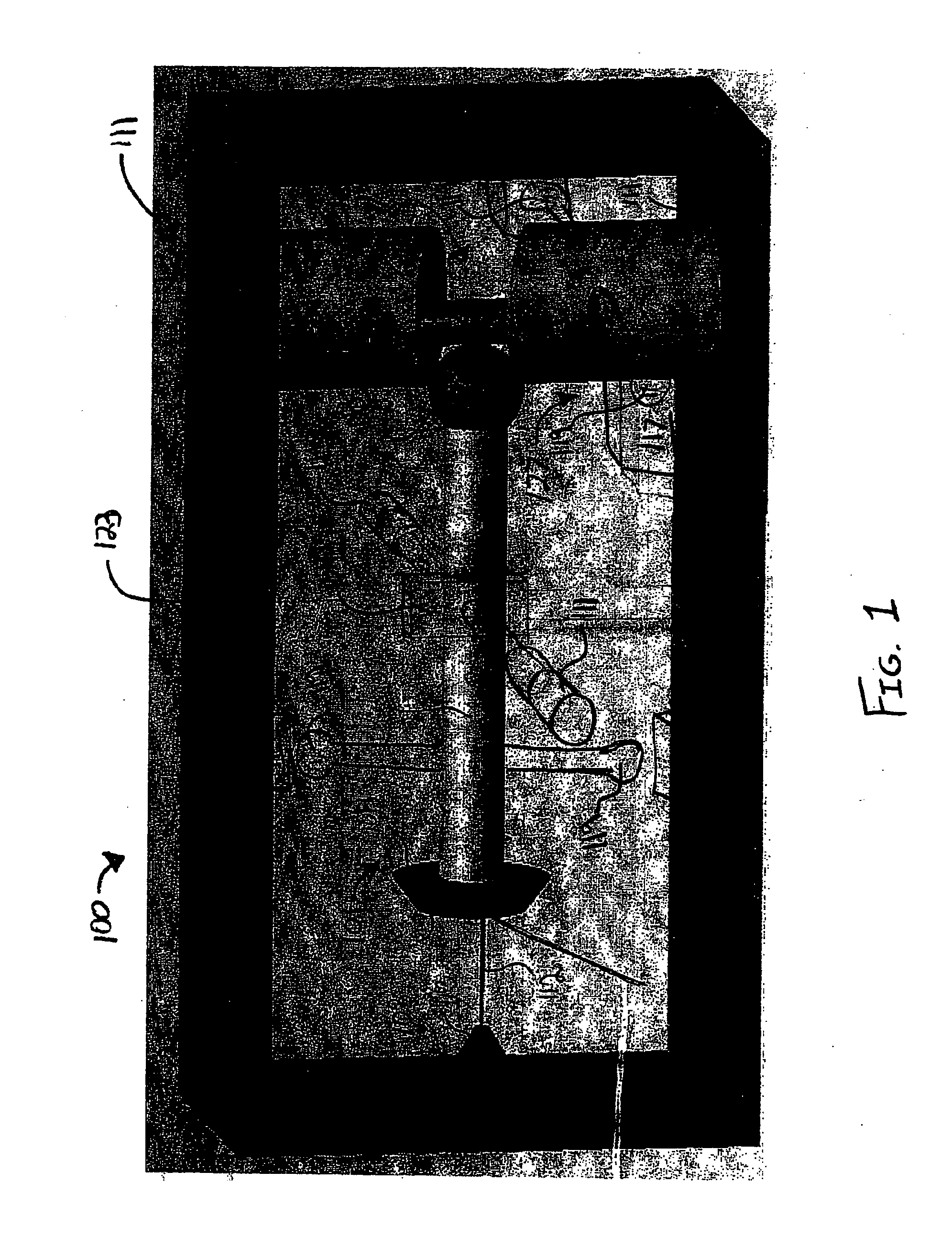
[0024]FIG. 1 is a perspective view of an X-ray tube assembly 100 having an anode assembly 101 and a cathode assembly 103. The anode assembly 101 and cathode assembly 103 are arranged in a manner, through thermionic or field-emission electron generation, that permits formation of X-rays, during X-ray tube assembly 100 operation. The anode assembly 101 includes an anode target 105 mounted on a support shaft 107. The anode target 105 is fabricated from any material suitable for use as an anode target, such as, but not limited to copper (Cu), iron (Fe), silver (Ag), chromium (Cr), cobalt (Co), tungsten (W), molybdenum (Mo), and their alloys. For example, tungsten or molybdenum having additive refractory metal components, such as, tantalum, hafnium, zirconium and carbon may be utilized. The suitable materials may also include oxide dispersion strengthened molybdenum and molybdenum alloys, which may further include the addition of the addition of graphite to provide additional heat storag...


PUM


Abstract

An X-ray tube anode target assembly (101) having a support shaft (107) connected to a pivot assembly (109) and a movable anode target (105) having a target surface (106) disposed at one end of the support shaft and a contact element (108) disposed at the opposite end of the support shaft. A first drive assembly (115) is operably arranged with respect to the support shaft to provide oscillatory motion to the anode target about a first axis substantially parallel to the support shaft and a drive cylinder (125) is operably arranged with respect to the contact element to provide a pivoting motion to the support shaft. A second drive assembly (127) is operably arranged with respect to the drive cylinder to provide an oscillatory motion to the drive cylinder, the second drive cylinder being further configured to provide a linear motion parallel to the first axis. The target surface is maintained at a substantially constant angle of impingement and maintains a substantially fixed distance from a cathode (103) during target motion.

Description

FIELD OF THE INVENTION[0001]This disclosure relates to an X-ray tube anode target assembly and, more particularly, to configuration and structures for imparting motion to an X-ray tube anode target assembly.BACKGROUND[0002]Ordinarily, an X-ray beam-generating device referred to as an X-ray tube comprises dual electrodes of an electrical circuit in an evacuated chamber or tube. One of the electrodes is an electron emitter cathode which is positioned in the tube in spaced relationship to an anode target. Upon energization of the electrical circuit generates a stream or beam of electrons directed towards the anode target. This acceleration is generated from a high voltage differential between the anode and cathode that may range from 60-450 kV, which is a function of the imaging application. The electron stream is appropriately focused as a thin beam of very high velocity electrons striking the anode target surface. The anode surface ordinarily comprises a predetermined material, for e...

Claims


Application Information

Patent Timeline
IPC IPC(8): H01J35/28H01J35/08
CPCH01J35/28H01J35/24H01J35/26
Inventor PATURI, PRASAD BALAJI NARASIMHAAHLAWAT, ANUPAM SINGHMURTHY, MAHESHWARA
Owner GENERAL ELECTRIC CO
Why Eureka
Try Eureka