Eureka AIR delivers breakthrough ideas for toughest innovation challenges, trusted by R&D personnel around the world.

Submersible aquatic algae cultivation system

a technology of cultivation system and aquatic algae, which is applied in the field of floating pond and cultivation system, can solve the problems of increasing the demand for energy, food and water, exacerbate environmental consequences, and add to the stretching of supplies, so as to achieve rapid growth and harvesting, and maintain the cost of operation, the effect of reducing the cost of harvesting

Active Publication Date: 2010-11-18
BUSSELL STUART
View PDF33 Cites 24 Cited by
  • Summary
  • Abstract
  • Description
  • Claims
  • Application Information

AI Technical Summary

Benefits of technology

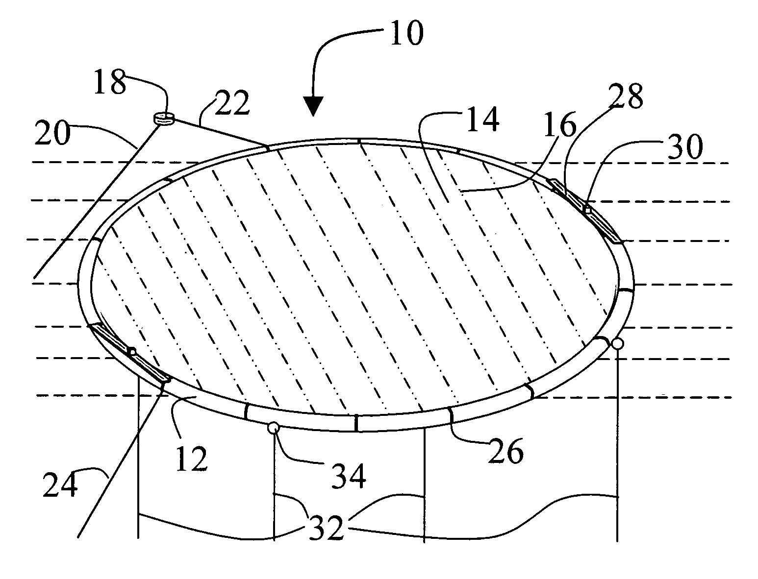
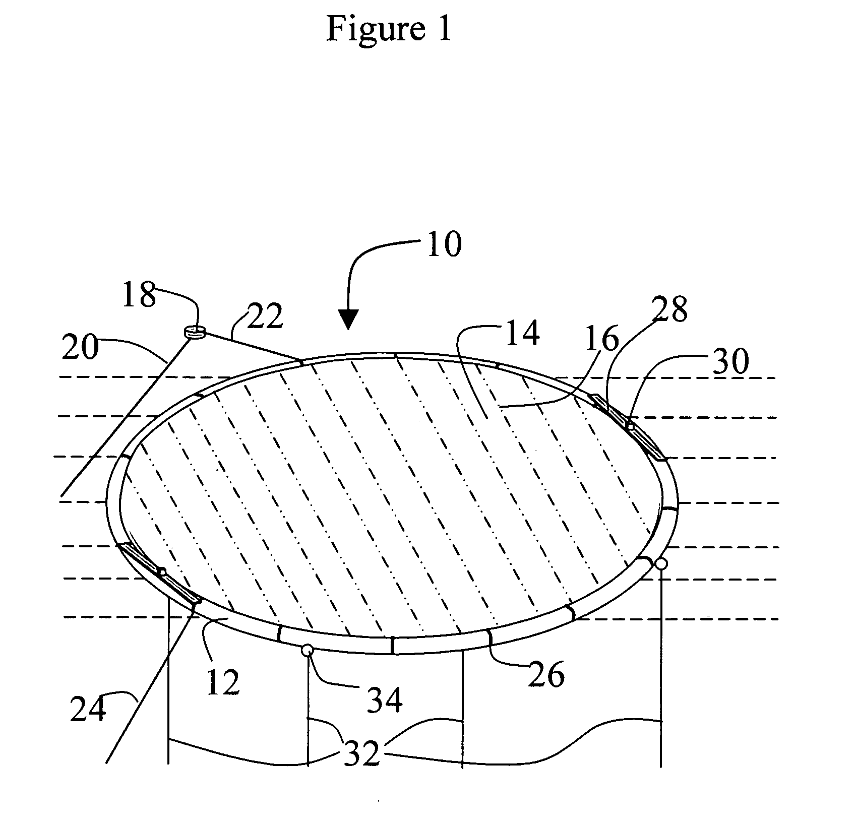
[0021]In its most general form, the current invention is a floating pond that can convert large areas of water into acreage for cultivating algae. It reduces the contributing costs of algae cultivation systems, some to almost insignificant levels. It does this in several cohesive ways.
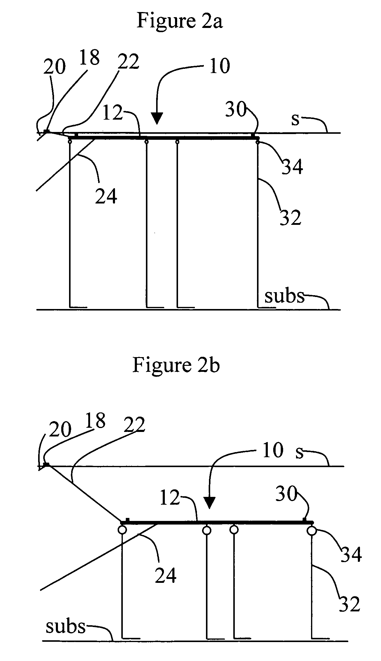
[0023]In another embodiment, the aquatic algae cultivation system is constructed from low weight bearing components, e.g. piping and plastic liner. Because the system is suspended in water, it has the advantage that it can be constructed, from low weight bearing components for the framework and less expensive components, e.g. plastic liner, to separate the pond from surrounding water. Exposure of components to floating or submerged conditions limits the weight and stresses to which they are exposed, thereby enabling use of materials and geometries unsuitable for terrestrial installation. Use of tubes and piping for the framework of the floating pond simplifies construction and scaling to large ponds. In some embodiments, the system is submersible, thereby protecting it during violent surface conditions. This enables it to avoid the costs of constructing it to survive worst case conditions. In this way, installation and maintenance costs are kept to a minimum. In some embodiments of the invention, the overall system is constructed of low cost repeating ponds that can be coupled together to give a virtually unlimited size farm.
[0025]Another embodiment of the present invention provides an algae cultivation system with a framework incorporating tubes that also function as ballast tanks and conduits to pump in nutrients and pump out the culture for harvest. In this way, operational costs, including harvesting, are kept to a minimum. In addition, when the system is submerged, ballast tanks are filled with the culture so that it can be used to quickly initiate growth and harvesting in the pond following submersion and surfacing processes.

Problems solved by technology

The world is experiencing increasing demand for energy, food, and water at a time of uncertain supplies.
This intensification adds to the stretching of supplies and exacerbates environmental consequences.
Continued future availability of energy is questionable at a time of intense use of non-renewable fossil fuels.
In addition, increased worldwide food demand stretches already thin supplies.
Fresh water for producing crops is scarce in many parts of the world, and natural food stocks like oceanic fisheries are being harvested faster than they can replenish themselves.
Biofuels are seen by many as a renewable replacement, or supplement, for fossil fuels, but problems need to be overcome.
However, so far none have been able to compete on a cost basis with fossil fuels.
In addition, use of agricultural crops for production of biofuels introduces the opportunity cost of diverting these resources from food production.
Despite these advantages, however, algae have failed to become an appreciable source of energy or food.
As demonstrated by an extensive multi-decade program by the United States National Renewable Energy Laboratory to develop algae for biofuels (Sheehan, 1998), a major problem with algae is the inability to produce large amounts of it at competitive prices.
Algae have failed to compete on a large scale with fossil fuels and traditional farming of plants for a number of reasons:1. since algae are aquatic, they can require large amounts of costly water,2. the costs of installing and maintaining an algae pond can be prohibitive,3. operational costs, including CO2 supplies and energy for mixing to operate high productivity ponds, can be prohibitive, and4. harvesting the algae from the ponds can be costly.
Expenses for nutrients, including CO2 gas, water, and power are some of the major operating costs of an open system of this design.
Substantial fixed costs, like the installation of the pond and the cost of the land underneath it, also contribute to making the costs of operating open systems prohibitive compared to conventional farms.
However, the evaporation in open systems provides a mechanism to cool the pond, and cost savings from using less water can easily be surpassed by more energy needed to cool the culture.
Because closed systems are more highly engineered, installation and maintenance costs of closed systems tend to be much higher than those for racetrack type open systems.
Finally, while yields can be higher for closed systems; the operational costs tend to be higher, mitigating or even reversing any potential benefits from the higher yields.
The problem with large scale use of hybrid systems is that they don't address the basic four cost disadvantages of open and closed systems listed above relative to conventional farming; they merely minimize these costs between themselves.
They fail to alter the basic cost advantages of conventional farms for the large scale production of biomass over existing designs for algae ponds.
While hybrid systems are capable of producing specialty products at the cheapest price, they have been unable to directly compete with conventional farms.
Harvesting of the algae, in this case, is impractical because of the dispersion of the algae through large volumes at low concentrations.

Method used


Image

  • Submersible aquatic algae cultivation system
  • Submersible aquatic algae cultivation system
  • Submersible aquatic algae cultivation system

Examples


example 1

[0093]The rectangular floating pond in FIG. 8 is useful for testing system components and culture maintenance procedures. It has relatively small surface area coverage and is not submersible. A convenient pond size is 10 meters wide by 100 meters long. The size is chosen so that the ratio of the width of the pond compared to the diameter of the longitudinal member is large enough for a representative current to establish itself. If this ratio is O(1), then the longitudinal members provide too much shelter against the wind and the current will be negligible. Also, the ratio of wave heights to the diameter of the longitudinal member cannot be significantly more than 1, or the waves will swamp the pond. As such, the pond of this example is designed for surrounding waves with limited significant wave heights.

[0094]The buoyant framework can be made from many different materials like UV resistant PE, HD, MD, or LD, UV resistant PVC, or other such material. The list included here is for il...

example 2

[0098]The floating pond depicted in FIG. 8 can be converted to a submersible pond with some additional system components already described. Additional valving, piping, and optionally air pumping capabilities, so that the culture and surrounding water can be pumped into and out of longitudinal member 132, enable adjustment of the pond's buoyancy. If materials of construction for the framework result in an average density of the pond greater than the surrounding water with longitudinal member 132 filled, then longitudinal tubes filled with air, like tubes 44 in FIG. 4b, will have to be added. Addition of submerging lines and spools then enable adjusting the orientation of the pond and its equilibrium submersion depth.


PUM


Abstract

Floating ponds for the cultivation of algae are disclosed. The floating ponds consist of a buoyant framework, a liner, a culture, and a mooring system. Submersible floating ponds are disclosed with a buoyant framework built from tubes that may be filled or partially filled with, for example, air, or water, or the surrounding water, or the culture, and thereby the present invention provides a framework in which the buoyancy may be modulated. Use of submerging lines and spools are disclosed to control the orientation and depth of the floating pond during submersion.

Description

CROSS REFERENCE TO RELATED APPLICATIONS[0001]This application claims priority to U.S. provisional application number U.S. 61 / 011,932, filed Jan. 23, 2008, naming Stuart Bussell as inventor.FIELD OF THE INVENTION[0002]This invention relates most generally to a cultivation system. The invention relates more specifically to a floating pond and a method for the cultivation of algae.BACKGROUND OF THE INVENTION[0003]The world is experiencing increasing demand for energy, food, and water at a time of uncertain supplies. Large populations in countries like India and China are undergoing industrialization, with the concomitant intensification of per capita resource utilization. This intensification adds to the stretching of supplies and exacerbates environmental consequences.[0004]Continued future availability of energy is questionable at a time of intense use of non-renewable fossil fuels. Known oil reserves are predicted to continue to decline, and global warming, caused in part by increas...

Claims


Application Information

Patent Timeline
Patent Type & Authority Applications(United States)
IPC IPC(8): A01G1/00
CPCA01G33/00C12M23/56C12M23/18C12M21/02Y02A40/80
Inventor BUSSELL, STUART
Owner BUSSELL STUART
Why Eureka
Eureka Blog
Learn More