Glass cutting apparatus, glass-substrate disassembling apparatus, glass-substrate disassembling system, glass cutting method, and glass-substrate disassembling method

a technology of glass substrates and cutting apparatuses, applied in the field of glass cutting apparatuses and a glass cutting method, can solve the problems of social challenges, sold panels which have been used have been subjected to disposal processing, and defective components created during panel fabrication processing, etc., and achieves the effects of simple method, high efficiency, and low cos

Inactive Publication Date: 2010-11-18
PANASONIC CORP
View PDF6 Cites 12 Cited by
  • Summary
  • Abstract
  • Description
  • Claims
  • Application Information

AI Technical Summary

Benefits of technology

[0016]According to the present invention, cut lines are formed in opposite surfaces of a glass with a pair of cutters installed oppositely to each other in a horizontal direction, which enables cutting a laminated glass or a hollow glass with a larger plate thickness, in a short period of time, without inducing flaws caused by horizontal cracks and chips in the cut surfaces, thereby offering an advantage of a possibility of disassembling a panel into two glass flat plates with a simple method and an inexpensive apparatus with higher efficiency.

Problems solved by technology

On the other hand, conventionally, defective components created during panel fabrication processing and sold panels which have been used have been subjected to disposal processing such as landfills.
However, regeneration and reuse of panels have been social challenges, due to an increase of public opinions for global environmental protection, such as effective utilization, regeneration, reuse and saving of resources, as well as a lack of landfill grounds.

Method used


Image

  • Glass cutting apparatus, glass-substrate disassembling apparatus, glass-substrate disassembling system, glass cutting method, and glass-substrate disassembling method
  • Glass cutting apparatus, glass-substrate disassembling apparatus, glass-substrate disassembling system, glass cutting method, and glass-substrate disassembling method
  • Glass cutting apparatus, glass-substrate disassembling apparatus, glass-substrate disassembling system, glass cutting method, and glass-substrate disassembling method

Examples


first embodiment

[0088]In the present embodiment, there will be described a glass-substrate disassembling system, by exemplifying a plasma display panel as an object to be processed.

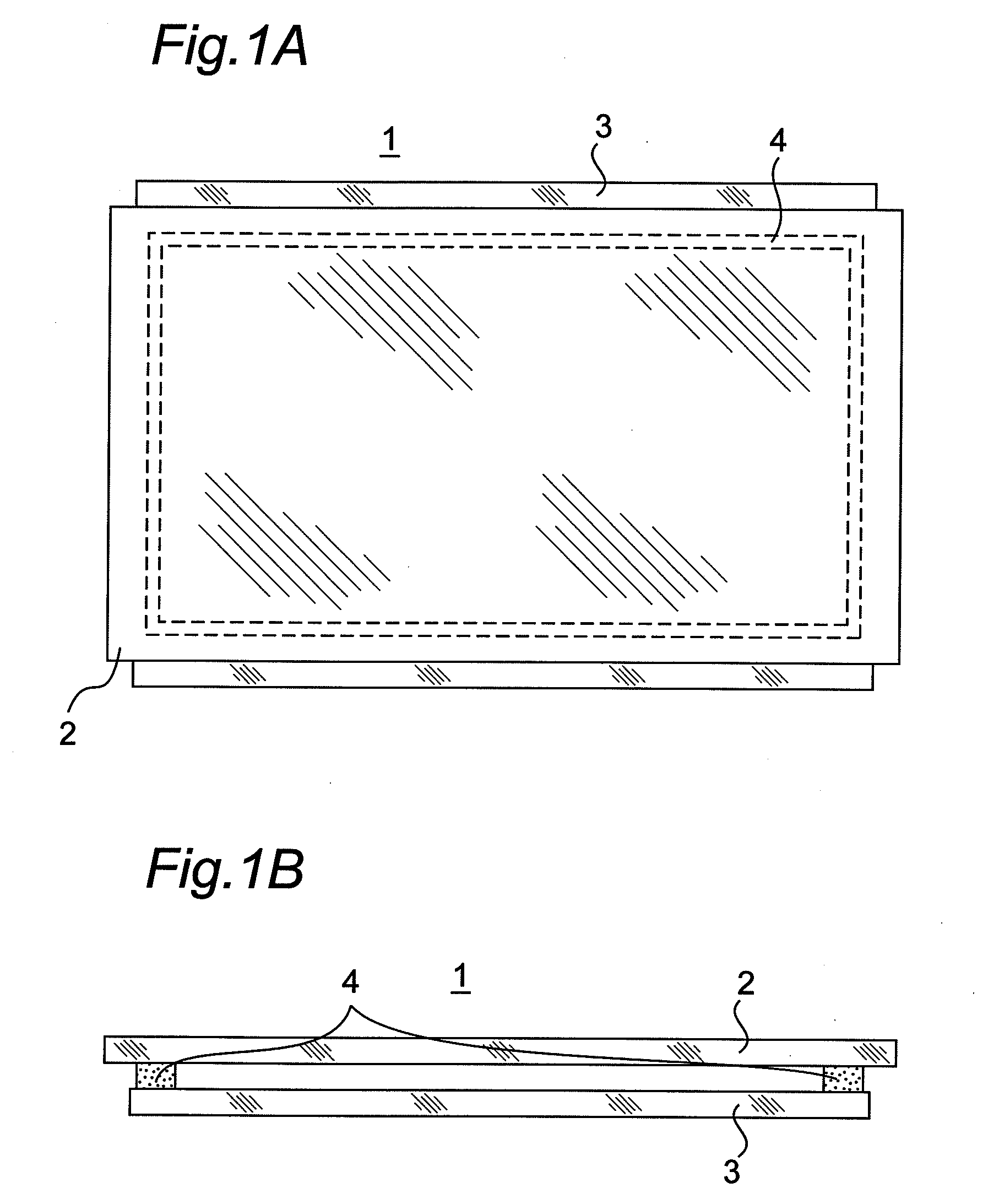
[0089]FIGS. 1A and 1B are schematic views of the structure of a plasma display panel 1 (hereinafter, referred to as a “panel 1”). FIG. 1A is a plan view of the panel 1, and FIG. 1B is a front view of the panel 1. The panel 1 includes a first glass flat plate 2 which is provided with pixel electrodes and is placed at the front surface, and a second glass flat plate 3 which is provided with pixel electrodes, further coated with a fluorescent material and is placed at the back surface. These glass flat plates 2 and 3 are attached to each other in a sealing manner through a bonding member 4 as a coupling member, at a state where a discharge gas is enclosed at a predetermined pressure within the space closed by the flat plates 2 and 3 and the bonding member 4. The bonding member 4 is applied to the glass flat plates 2 and 3, ...

second embodiment

[0116]In the present embodiment, there will be described a glass cutting apparatus capable of splitting a laminated glass or a hollow glass with a larger plate thickness, in a short period of time, without inducing glass particles, flaws caused by horizontal cracks, and chips in the cut surfaces.

[0117]FIG. 13 is a schematic cross-sectional view illustrating main parts of an exemplary structure of the glass cutting apparatus according to the second embodiment of the present invention. FIGS. 14 to 17 are views illustrating a glass cutting method according to the present invention, by exemplifying a case of employing the glass cutting apparatus illustrated in FIG. 13.

[0118]Referring to FIG. 13, a laminated glass 1 is constituted by two glass flat plates 2 and 3 opposing to each other, and a bonding member 4 bonding these glass flat plates 2 and 3 to each other. The bonding member 4 is made of a flit glass, or an epoxy resin adhesive agent. The glass-plate holding unit 7 (namely, the fi...

third embodiment

[0139]It is desirable that, in the glass cutting apparatus according to the second embodiment, the depths of the vertical cracks formed in the glass flat plates 2 and 3 at the time of cutting them are equal to each other. In order to attain this, it is necessary that the wheel cutters 13a and 13b are pressed against the glass flat plates 2 and 3 with the same pressure. However, even when the pressing forces of the first pressing unit 14a and the second pressing unit 14b are controlled such that they are equal to each other, the upper first wheel cutter 13a is subjected to its own weight, which prevents the actual pressing forces applied to the first and second wheel cutters 13a and 13b from being equal to each other. Therefore, in order to actually apply the same pressing force to the wheel cutters 13a and 13b, it is necessary to control the pressing forces of the first pressing unit 14a and the second pressing unit 14b, taking in account the weight of the first wheel cutter 13a, th...


PUM

PropertyMeasurementUnit
thicknessaaaaaaaaaa
widthaaaaaaaaaa
thicknessaaaaaaaaaa

Abstract

A glass cutting apparatus (101) includes a pair of cutters (13a, 13b) installed oppositely to each other in such a way as to sandwich, therebetween, a glass plate with surfaces of the glass plate thereof being along a vertical direction; a first pressing unit (14a) which presses one of the cutters to one of the surfaces of the glass plate in a horizontal direction with a pressing force P; a second pressing unit (14b) which is placed oppositely to the first pressing unit and presses the other one of the cutters to the other surface of the glass plate in the horizontal direction with the pressing force P; and a moving unit (20) which moves the pair of cutters pressing the glass plate with the pressing force P.

Description

TECHNICAL FIELD[0001]The present invention relates to a glass cutting apparatus and a glass cutting method for cutting a glass plate, and also relates to a glass-substrate disassembling apparatus, a glass-substrate disassembling system and a glass-substrate disassembling method which use the glass cutting apparatus. More specifically, the present invention relates to a glass cutting apparatus and a glass cutting method for cutting a laminated glass constituting a display panel, which is configured by two glass flat plates attached to each other with a spacing provided therebetween, to recycle the display panel, and also relates to a glass-substrate disassembling apparatus, a glass-substrate disassembling system and a glass-substrate disassembling method for disassembling the laminated glass into the respective glass flat plates using the glass cutting apparatus.BACKGROUND ART[0002]In recent years, attention has been focused on plasma display panels and liquid crystal display panels,...

Claims


Application Information

Patent Timeline
Patent Type & Authority Applications(United States)
IPC IPC(8): B26D3/08B23P19/04B28D5/00C03B33/07G02F1/13G02F1/1333H01J9/50H01J17/16
CPCB65G2249/04Y10T29/49821C03B33/03C03B33/033C03B33/076G02F1/1303G02F1/133351H01J9/52H01J2217/49H01J2329/00Y10T29/49815Y10T29/49819Y10T29/49822Y10T29/53Y10T29/534Y10T29/54C03B33/0207Y02W30/60Y10T83/0363Y10T225/325Y02W30/82
Inventor IWAMOTO, HIROSHITANI, YOSHIYUKIYAMAZAKI, FUMIOHISAZUMI, TAKAO
Owner PANASONIC CORP
Why Eureka
Try Eureka