Optical recording medium and method for manufacturing the same

Inactive Publication Date: 2010-11-18
SONY CORP
View PDF4 Cites 2 Cited by
  • Summary
  • Abstract
  • Description
  • Claims
  • Application Information

AI Technical Summary

Benefits of technology

[0019]In the embodiments according to the present invention, not only the barrier layer for suppressing the gas release on the second principal surface of the substrate is formed, but an area of the region exposing from the barrier layer of the second principal surface of the substrate is set to be not more than 688 mm2. According to this, in forming the information signal recording layer, degassing within the substrate can be efficiently suppressed. For that reason, in forming the information signal layer, deterioration of a degree of vacuum to be caused d

Problems solved by technology

However, in the case where the number of times of recording increases, there is in general a tendency that thermal damage is accumulated in the phase-charge recording layer, a function to perform a reversible change between the crystalli

Method used


Image

  • Optical recording medium and method for manufacturing the same
  • Optical recording medium and method for manufacturing the same
  • Optical recording medium and method for manufacturing the same

Examples


first embodiment

1. First Embodiment

Configuration of Optical Recording Medium

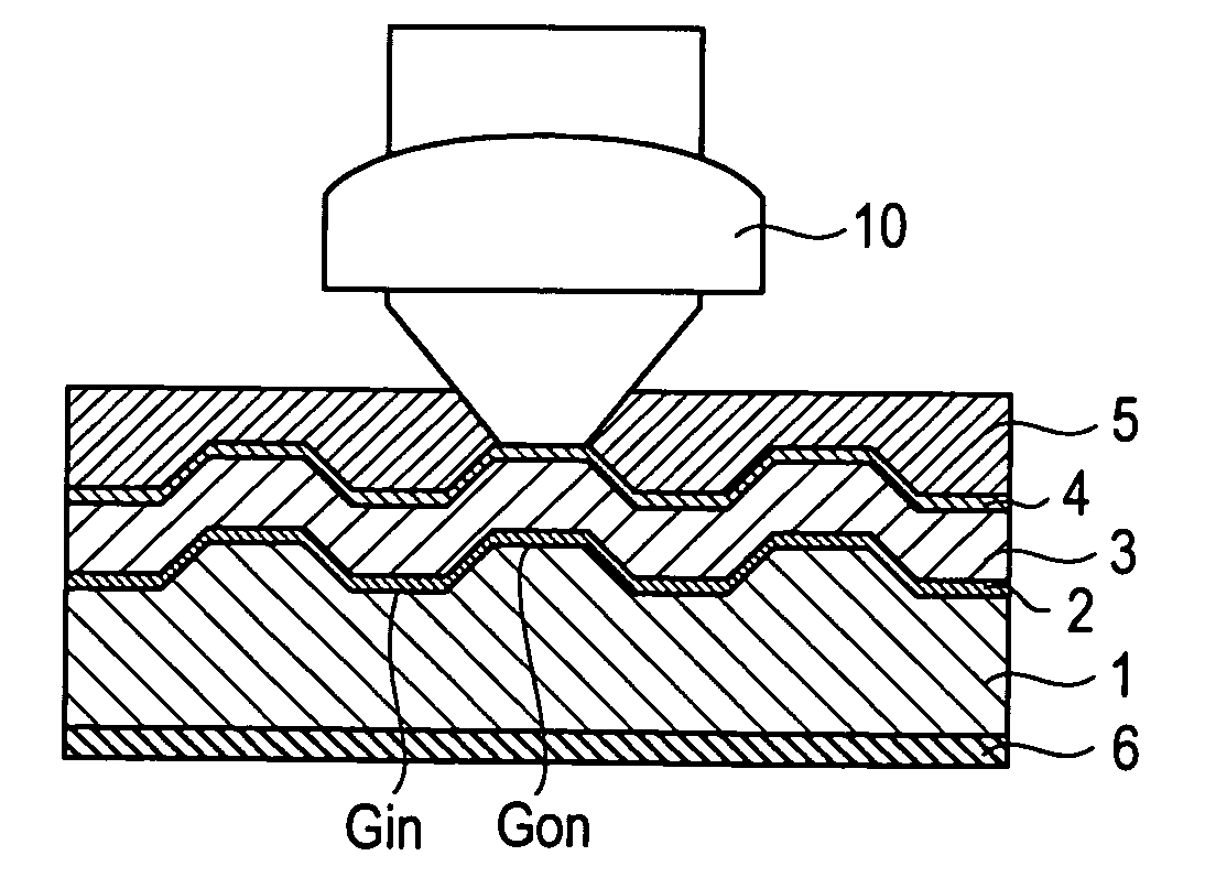
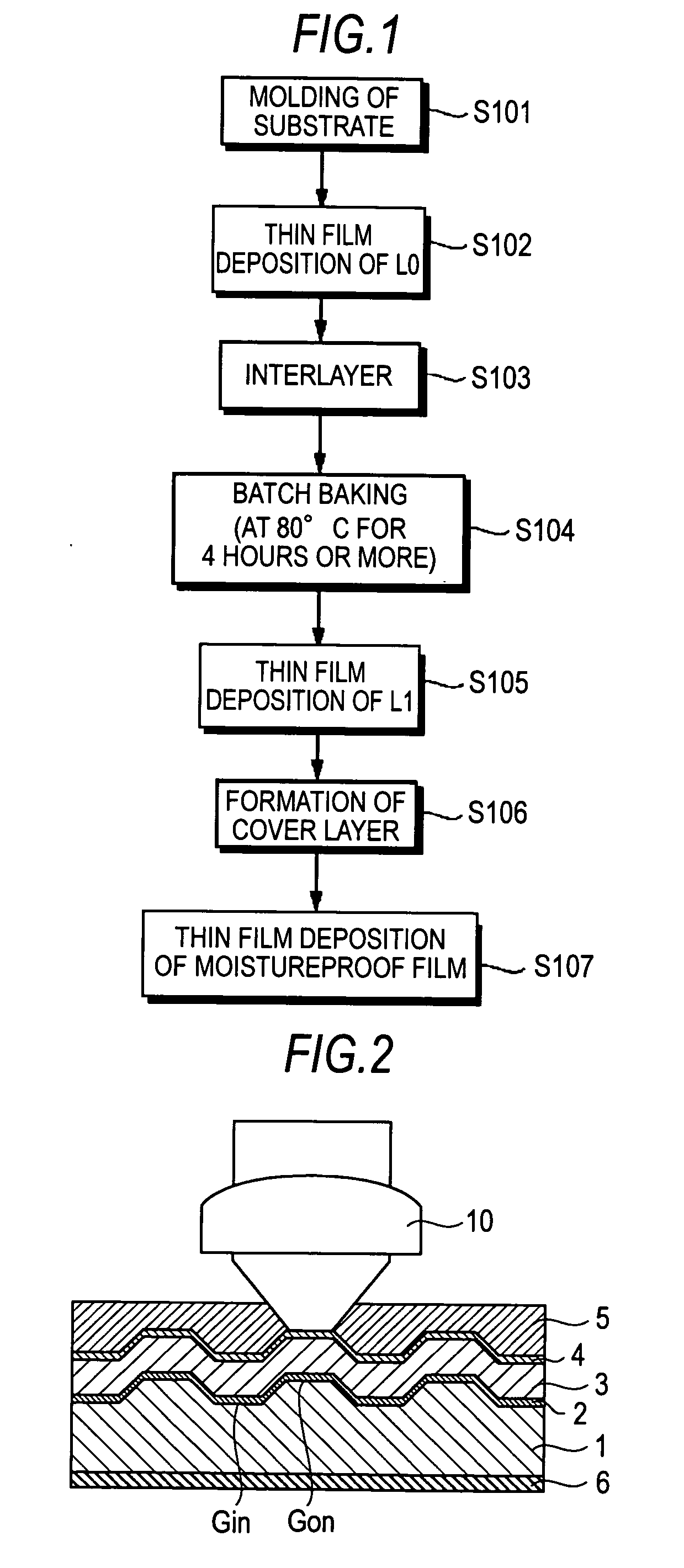
[0037]FIG. 2 shows a configuration example of an optical recording medium according to the first embodiment of the present invention. This optical recording medium is a rewritable optical recording medium capable of erasing or rewriting data. As shown in FIG. 2, the optical recording medium includes a substrate 1; a first information signal layer (L0 layer) 2, an interlayer 3, a second information signal layer (L1 layer) 4 and a cover layer 5 laminated in this order on one principal surface (first principal surface) of the substrate 1; and a barrier layer 6 laminated on the other principal surface (second principal surface) of the substrate. Hereinafter, one principal surface of the substrate 1 on which the first information signal layer 2 and the second information signal layer 4 are laminated is properly referred to as “signal surface”; and the other principal surface on the opposite side thereto is properly referred to a...

second embodiment

2. Second Embodiment

[0082]FIG. 8 shows a configuration example of the optical recording medium according to the second embodiment of the present invention. As shown in FIG. 8, the optical recording medium according to the second embodiment is different from that of the first embodiment in the point that it includes a single-layer information signal layer 7. The same symbols are given to the same portions as those in the foregoing first embodiment, and their explanations are omitted. As the information signal layer 7, for example, the same layer as the first information signal layer 2 in the first embodiment can be used. In this second embodiment, the barrier layer 6 is, for example, formed after the step of molding the substrate 1 but before the step of forming the information signal layer 7.

[0083]According to this second embodiment, the durability against repeated recording can be enhanced in a single-layer rewritable optical recording medium.

example 1

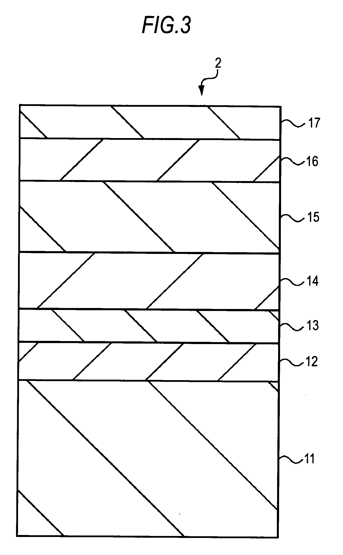
[0085]First of all, a polycarbonate substrate having a diameter φ of 120 mm and a thickness of 1.1 mm and provided with grooves having a track pitch of 0.32 μm was molded by an injection molding apparatus. This polycarbonate substrate is in conformity with Blu-ray Disc Rewritable Format, Part 1: Basic Format Specifications Version 2.1. Subsequently, the molded substrate was conveyed into a first single sputtering apparatus (DVD SPRINTER, manufactured by Oerlikon) from the injection molding apparatus. Subsequently, a reflecting layer, a second dielectric layer, a first dielectric layer, a phase-change recording layer, a first dielectric layer and a second dielectric layer each having the following composition and film thickness were laminated in this order on the surface of the substrate in a magnetron sputtering mode. There was thus formed a first information signal layer (L0 layer) on the surface of the substrate.

[0086]Second dielectric layer: SiN, 40 nm

[0087]First dielectric layer...


PUM


Abstract

An optical recording medium includes: a substrate having a first principal surface and a second principal surface; one or plural information signal layers formed on the first principal surface of the substrate for undergoing recording or reproduction of information signals upon irradiation with light; and a barrier layer formed on the second principal surface of the substrate for suppressing the gas release from the second principal surface of the substrate, wherein an area of a region exposing from the barrier layer of the second principal surface of the substrate is not more than 688 mm2.

Description

BACKGROUND OF THE INVENTION[0001]1. Field of the Invention[0002]The present invention relates to an optical recording medium and a method for manufacturing the same. In detail, the present invention relates to an optical recording medium for undergoing recording and / or reproduction of information signals upon irradiation with light.[0003]2. Description of the Related Art[0004]Rewritable optical recording media for undergoing reading or writing information signals upon irradiation with laser light on an information signal layer have hitherto widely spread. In general, for information recording layers used in rewritable Blu-ray Disc and the like, a phase-change recording material in which a reversible change occurs between a crystalline phase and an amorphous phase upon irradiation with laser light is used (see, for example, JP-A-2006-18926). In this phase-change recording material, it is possible to form the amorphous phase (recording mark) by sharply decreasing a temperature of a re...

Claims


Application Information

Patent Timeline
IPC IPC(8): B32B3/02G11B7/26G11B7/24G11B7/24038G11B7/24047G11B7/24053G11B7/243G11B7/2433G11B7/2533G11B7/254G11B7/2548G11B7/257
CPCG11B7/24053G11B7/26G11B2007/24312G11B2007/24314Y10T428/21G11B2007/25706G11B2007/25708G11B2007/2571G11B2007/25715G11B2007/24316
Inventor SUWABE, MASATSUGUNAKAYAMA, HIROSHIIGARI, TAKAHIROOTA, TERUYUKI
Owner SONY CORP
Why Eureka
Try Eureka