Conductive paste for solar cell electrode

a solar cell and electrode technology, applied in the field of photovoltaic cells, can solve problems such as the decrease of optical conversion efficiency, and achieve the effect of improving optical conversion efficiency and increasing the light-receiving area

Inactive Publication Date: 2010-11-25
EI DU PONT DE NEMOURS & CO
View PDF7 Cites 35 Cited by
  • Summary
  • Abstract
  • Description
  • Claims
  • Application Information

AI Technical Summary

Benefits of technology

[0011]If the present invention is used, an electrode having a large aspect ratio can be formed, and impr

Problems solved by technology

However, if the line width is merely narrowed, a decrease in cross-sectional area of the electrode wil

Method used


Image

  • Conductive paste for solar cell electrode
  • Conductive paste for solar cell electrode
  • Conductive paste for solar cell electrode

Examples


examples

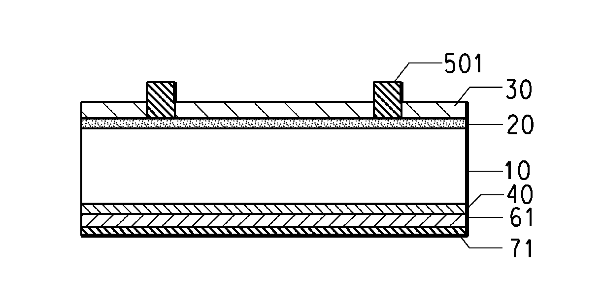
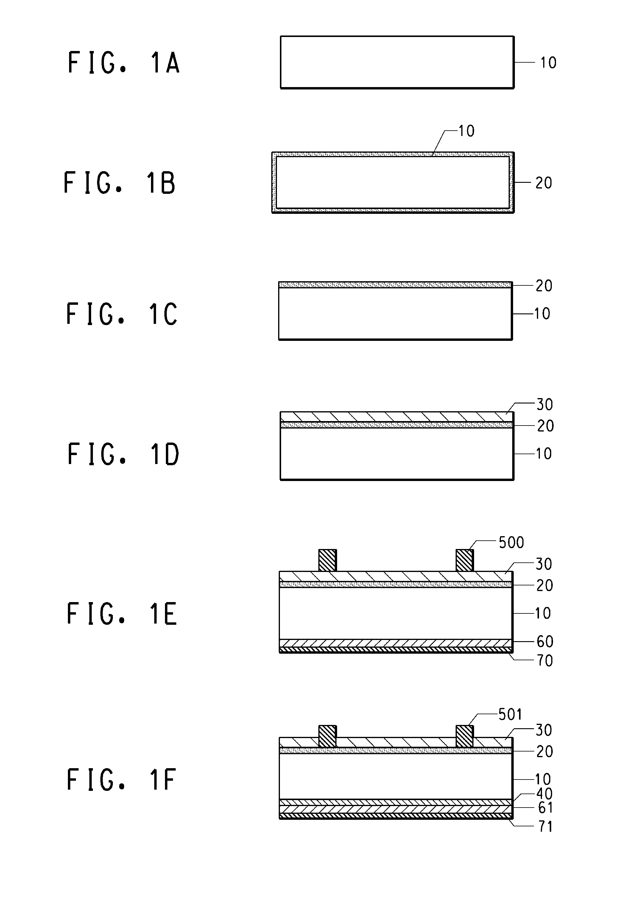
[0058]Examples of the electrode of the present invention are described herein below.

(A) Conductive Paste Preparation

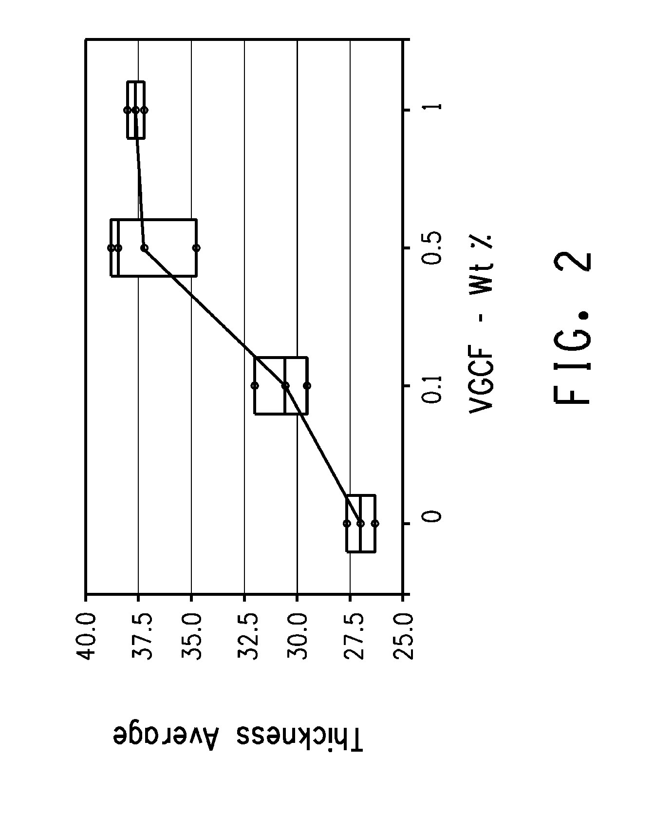
[0059]Used material in the paste preparation and the content of each component are as follows:[0060]I. Electrically functional conductive powder: A mixture of 24% of spherical silver powder [d50 2.3 μm as determined with a laser scattering-type particle size distribution measuring apparatus] and 56% of flake silver powder [d50 2.9 μm] were used. The total content of the silver powder was 80 wt % of the conductive paste.[0061]II. Glass Frit: Si—Pb—B based glass frit was used. The total content of the glass frit was adjusted depending on the content of the inorganic fiber as shown in Table 1.[0062]III. Organic Medium: An organic medium consisting of mainly Ethyl cellulose resin and texanol was used. The content of the organic medium was 10 wt % of the conductive paste.[0063]IV. Inorganic fiber: A carbon fiber (VGCF-H, Showa Denko K. K.) having a diameter of 150 nm, a len...


PUM


Abstract

An electrode formed on the light-receiving side of photovoltaic cell, comprising conductive component, glass binder, and carbon fiber or metal fiber. By including a carbon fiber and a metal fiber, an electrode having a high aspect ratio can be formed, and improvement of optical conversion efficiency through an increase in light-receiving area can be expected.

Description

FIELD OF THE INVENTION[0001]This invention relates to photovoltaic cell, and in particular, relates to improvement of conductive paste for electrode.TECHNICAL BACKGROUND OF THE INVENTION[0002]One of the widely-used solar cells currently is silicon solar cells. The manufacturing process of the silicon solar cells typically includes the formation of electrode by use of conductive paste.[0003]Generally, the conductive paste includes a conductive particle such as silver, inorganic binder such as glass frit, organic medium and optional other additives.[0004]Since the electric generating capacity of solar cells increases as the light-receiving area thereof increases, it is preferable for the front electrode formed on the light-receiving area to have a narrow line width. However, if the line width is merely narrowed, a decrease in cross-sectional area of the electrode will end up increasing electrode resistance and will thus end up decreasing optical conversion efficiency. Therefore, there...

Claims


Application Information

Patent Timeline
IPC IPC(8): H01L31/0224H01L31/00H01L31/18
CPCC09D5/24C09D11/0235Y02E10/50H01B1/24H01L31/022425H01B1/22
Inventor TAKAHASHI, RYOICHIRO
Owner EI DU PONT DE NEMOURS & CO
Why Eureka
Try Eureka