Table gauge

a table gauge and meter technology, applied in the field of optical imaging systems, can solve the problems of uneven illumination, high labor intensity, and poor image quality, and achieve the effects of high reflectivity, low labor intensity, and high resolution images

Inactive Publication Date: 2010-11-25
INNOVATIVE IMAGING
View PDF33 Cites 7 Cited by
  • Summary
  • Abstract
  • Description
  • Claims
  • Application Information

AI Technical Summary

Benefits of technology

[0022]Suitable materials and/or coatings for housing 3, 4 are known to skilled persons. In the embodiment shown, housing 3, 4 is formed from a lower housing 4 and a shroud 3 which may be removed from, or adjusted relative to, lower housing 4 for placement of an object on the object inspection site 5. For imaging or inspection, shroud 3 may be located atop lower housing 4 to form a functional housing 3, 4 as described above.
[0023]Object inspection site 5 is located within housing 3, 4, preferably substantially at the location of a focus plane of camera 6. Object inspection site 5 may include any suitable object inspection site. In the embodiment of FIG. 1, object inspection site 5 is provided by a transparent surface on which an object may be placed for analysis. Preferably, this type of object inspection site 5 is constructed from a substantially non-reflective transparent material having a reflectivity of about 6% or less, more preferably a non-reflective transparent material, most preferably a non-reflective glass or plastic surface having a reflectivity of about 2% or less. The percent reflectivity may vary depending on the wavelength of light employed, e.g. some materials exhibit a higher reflectivity for infrared light as compared to visible light.
[0024]The transparent surface of object inspection site 5 may have any suitable dimension that accommodates the object being imaged. Typically, the transparent surface is larger than the object area which is illuminated by the light source. Optionally, object inspection site 5 may also include a contoured surface area for cradling an object to be imaged or retention structures for retaining an object during imaging, such as fasteners, belts or clamps if it is desired to fix the object in a particular position for imaging or inspection.
[0025]In other embodiments, such as that shown in FIG. 3, object inspection site 5 may be provided by apparatus for holding, positioning or supporting the object to be inspected. Thus, for example, in FIG. 3, object inspection site 5 is provided by two bars 11 which may be used to support an object at the focus plan...

Problems solved by technology

Such systems have degraded performance for a variety of reasons and suffer from problems such as magnification variance, variant optical distortion and poor, uneven illumination.
Furthermore, many standard imaging systems are only capable of accommodating objects, and sample sets, having specific overall dimensions, thus requiring great care in sample preparation and requiring recalibration of the system for each object should optical magnificati...

Method used


Image

  • Table gauge
  • Table gauge
  • Table gauge

Examples


example 1

Inspection of Polyvinyl Chloride (PVC) Pipe

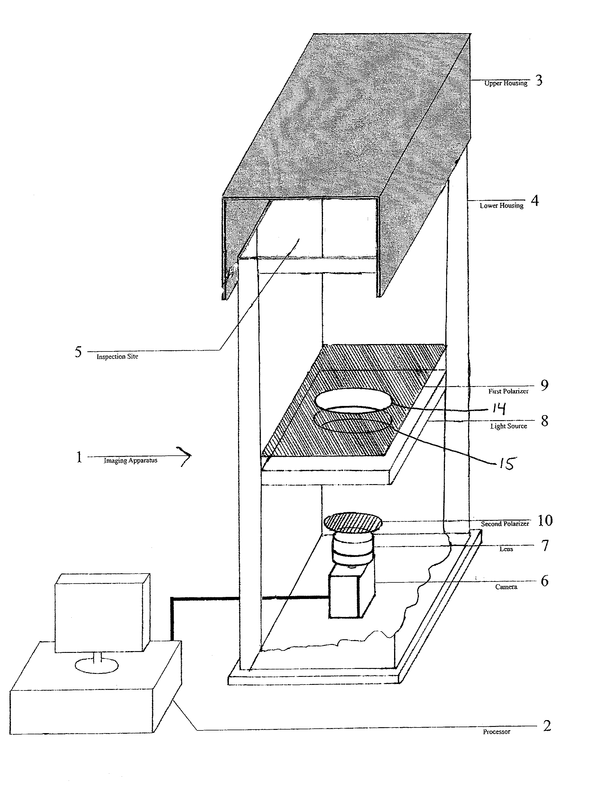
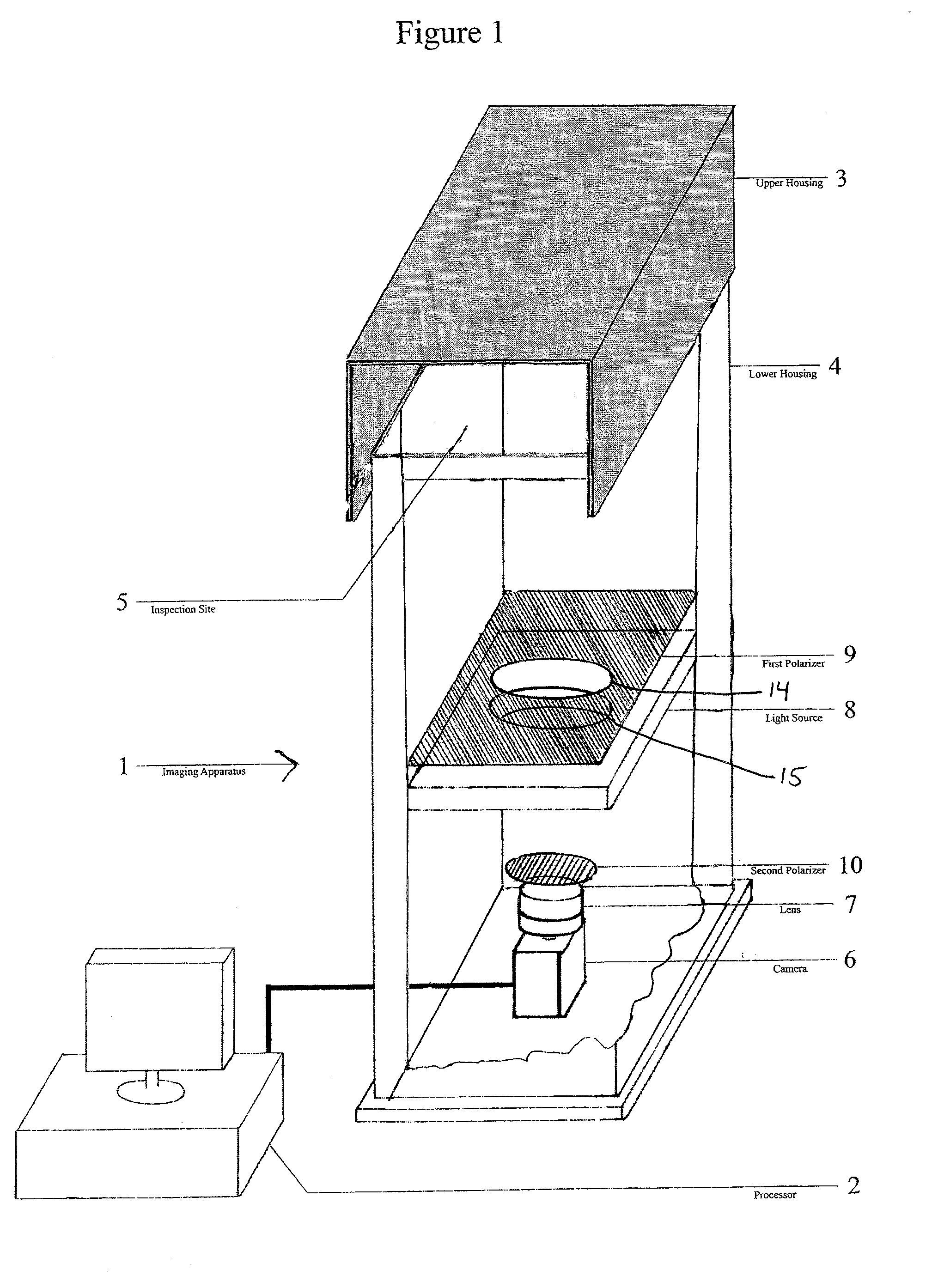
[0050]A device in accordance with FIG. 1 of the present application was assembled and tested for inspection of PVC pipe. Specifically, the goal was to accurately measure the thickness of coatings applied to a sample section of PVC pipe that had been cut by a saw blade from a larger section of manufactured PVC pipe. Many conventional inspection devices cannot perform this operation because the light reflections from ridges in the PVC pipe left behind by the saw blade cutting the pipe interfere with observation of the coatings on the pipe, making such observation difficult. The present invention, however, employs highly diffuse illumination in combination with polarizes to substantially eliminate light reflection from surface imperfections, such as the ridges left behind by the saw blade cutting the PVC pipe.

[0051]As a result, the device of the present invention was able to accurately measure the coating thicknesses of coatings applied to the...

example 2

[0052]The device in accordance with FIG. 1 of the present application employed in Example 1 was also tested for inspection of leather samples for manufacturing defects in the leather. Again, this is a difficult exercise for many conventional inspection systems because the natural surface texture and surface patterns of the leather may be easily mistaken for defects in the leather using such conventional inspection systems.

[0053]The device of the present invention, by virtue of its use of highly diffuse illumination, substantially eliminates the effects of surface textures and patterns on the leather from the image. It was found that certain types of defects in the leather could also be exposed by use of dark field illumination. Thus, the present device was demonstrated to be useful for leather inspection.

[0054]The device should be similarly useful for inspection of soft, flexible materials such as fabrics since distortion of the image is minimized by the fact that the object can be ...


PUM


Abstract

A high resolution imaging system and method for using it. More specifically, the present invention relates to an imaging system including an imaging apparatus, a processor and a various features to minimize reflected and ambient light producing consistent, high fidelity images to facilitate high resolution imaging. The system may be used for material inspection and may be particularly beneficial for enlarging an image of an object, determining the geometry or morphology of an object surface, or enabling precise measurement of a feature of an object.

Description

FIELD OF THE INVENTION[0001]The present invention relates to the fields of inspection, imaging and image analysis. More specifically, the present invention relates to an optical imaging system for material inspection and methods for using it.BACKGROUND OF THE INVENTION[0002]Imaging apparatus comprising cameras, light sources and data analysis instruments are used in a variety of industries and applications, for both off-line and inline inspections. Current imaging systems typically have a downward looking camera and lighting to view an object positioned on a surface below the image sensor. Such systems have degraded performance for a variety of reasons and suffer from problems such as magnification variance, variant optical distortion and poor, uneven illumination.[0003]Additionally, current systems incorporate cameras, optics, and lighting configured for specific objects and object sizes which generally require careful and repeatable placement and restraint of the object. Objects m...

Claims


Application Information

Patent Timeline
IPC IPC(8): H04N7/18
CPCG01N21/01G01B11/24
Inventor HOONING, JOHN E.VU, TONY TUAN
Owner INNOVATIVE IMAGING
Why Eureka
Try Eureka