Fuel reforming apparatus

a technology of fuel reforming apparatus and concentration sensor, which is applied in the direction of gas modification by gas mixing, gaseous engine fuel, hydrogen/synthetic gas production, etc., can solve the problems of reducing detection accuracy, small size, and inexpensive concentration sensor that could be mounted in the prior art fuel reforming apparatus, and achieves accurate calibration of sensor output characteristics, continuous detection, and high accuracy

Active Publication Date: 2010-12-02
TOYOTA JIDOSHA KK
View PDF9 Cites 34 Cited by
  • Summary
  • Abstract
  • Description
  • Claims
  • Application Information

AI Technical Summary

Benefits of technology

[0049]In accordance with the eleventh aspect of the present invention, the gaseous material supply means can easily produce an oxygen-free state and atmospheric air supply state in which an air-fuel ratio sensor output can be calibrated. The first oxygen error detection means can detect the amount of deviation between a sensor signal value and zero-point reference value in the oxygen-free state. Further, the second oxygen error detection means can detect the amount of deviation between the sensor signal value and atmospheric air reference value in a state where atmospheric air having a known oxygen concentration is supplied to an air-fuel ratio sensor.
[0050]The output characteristics of the air-fuel ratio sensors are linear with respect to the oxygen concentration. Therefore, the oxygen signal calibration means can accurately calibrate the output characteristics of the sensors with respect to the oxygen concentration by using the amounts of deviation in two different states, namely, the aforementioned oxygen-free state and atmospheric air supply state. Consequently, the oxygen concentration can be continuously detected with high accuracy even when the air-fuel ratio sensors are deteriorated. Further, the accuracy of hydrogen concentration detection can also be increased by increasing the accuracy of oxygen concentration detection.
[0051]In accordance with the twelfth aspect of the present invention, the reforming fuel supply means, gaseous material supply means, and adjustment means can be used to easily produce an oxygen-free, hydrogen-free state where sensor output calibration can be effected with respect to the hydrogen concentration and an oxygen-free state where hydrogen having a predefined concentration is supplied. The first hydrogen error detection means can detect the amount of deviation between a sensor signal value and zero-point reference value in the oxygen-free, hydrogen-free state. Further, the second hydrogen error detection means can detect the amount of deviation between a sensor signal value and nonzero-point reference value in the oxygen-free, predefined hydrogen supply state.
[0052]The output characteristics of the air-fuel ratio sensors are also linear with respect to the hydrogen concentration. Therefore, the hydrogen signal calibration means can accurately calibrate the output characteristics of the sensors with respect to the hydrogen concentration by using the amounts of deviation in two different states, namely, the aforementioned oxygen-free, hydrogen-free state and oxygen-free, predefined hydrogen supply state. Consequently, the hydrogen concentration can be continuously detected with high accuracy even when the air-fuel ratio sensors are deteriorated.
[0053]In accordance with the thirteenth aspect of the present invention, the catalyst diagnosis means can compare a value of a hydrogen concentration detected in the predefined catalyst diagnosis state against the predefined diagnosis reference value. Therefore, the catalyst diagnosis means can run a diagnostic check on the operation of the fuel reforming catalyst in accordance with the amount of hydrogen concentration deviation from the diagnosis reference value. In this instance, a diagnostic check can be accurately performed on the catalyst because the two air-fuel ratio sensors can accurately detect the hydrogen concentration. This makes it possible to certainly grasp, for instance, the deterioration of the fuel reforming catalyst, thereby providing enhanced reliability.
[0054]In accordance with the fourteenth aspect of the present invention, an air-fuel ratio sensor used during air-fuel ratio feedback control in an internal combustion engine can double as the upstream air-fuel ratio sensor for hydrogen concentration detection. Therefore, even when the two air-fuel ratio sensors are used for hydrogen concentration detection, it is possible to minimize an increase in the number of sensors and other parts, thereby contributing to further system simplification and cost reduction.

Problems solved by technology

However, a small-size, inexpensive concentration sensor that could be mounted in the prior art fuel reforming apparatus does not readily achieve high detection accuracy.
Further, when an operation is performed to detect the concentration of hydrogen, oxygen and other components contained in the combustible gas may affect the detection operation, resulting in a decrease in detection accuracy.

Method used


Image

  • Fuel reforming apparatus
  • Fuel reforming apparatus
  • Fuel reforming apparatus

Examples


first embodiment

Configuration of First Embodiment

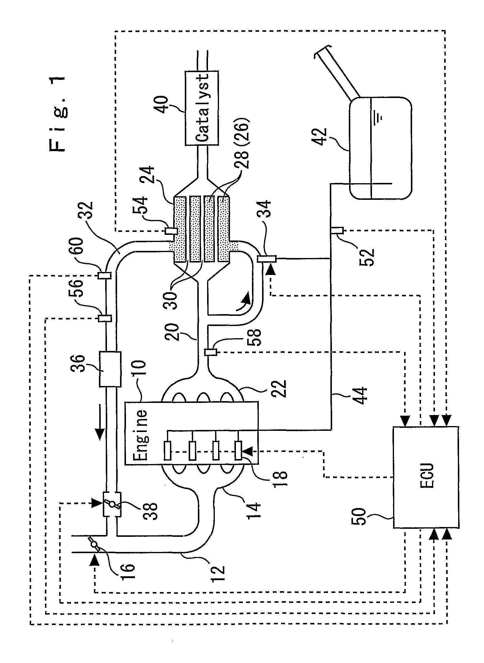
[0067]A first embodiment of the present invention will now be described with reference to FIGS. 1 to 11. FIG. 1 is an overall configuration diagram illustrating the configuration of a system according to the first embodiment. The system according to the present embodiment includes, for instance, a multi-cylinder internal combustion engine 10. This internal combustion engine 10 operates on a fuel mixture of alcohol and gasoline. The present embodiment assumes that a fuel mixture of ethanol and gasoline is used.

[0068]An intake pipe 12 of the internal combustion engine 10 is connected to an intake port of each cylinder through an intake manifold 14. An electric throttle valve 16 is installed in the middle of the intake pipe 12 to adjust the amount of intake air. The intake port of each cylinder is provided with a main fuel injection valve 18, which is composed, for instance, of a solenoid valve for fuel injection.

[0069]An exhaust pipe 20 of the internal...

second embodiment

[0169]A second embodiment of the present invention will now be described with reference to FIG. 12. The second embodiment uses the same system configuration (FIG. 1) as the first embodiment, but differs from the first embodiment in the structure of the downstream air-fuel ratio sensor.

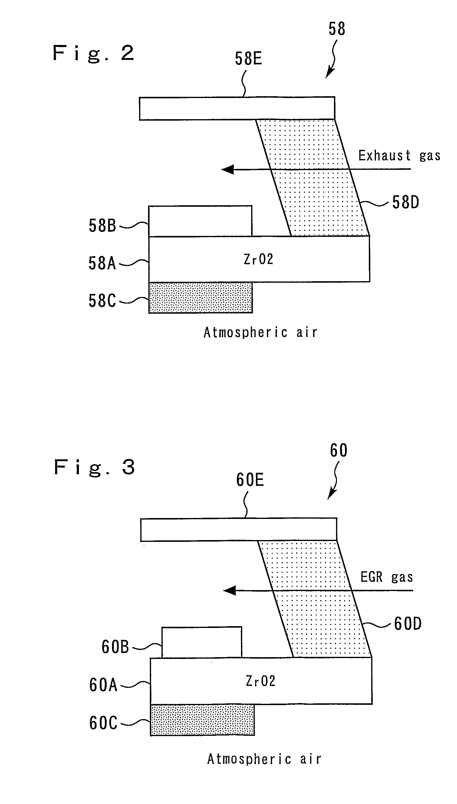
[0170]The downstream air-fuel ratio sensor 70 according to the second embodiment is similar to the counterpart according to the first embodiment in that the former includes a detection element 70A, electrodes 70B, 70C, a diffusion layer 70D, and a housing 70E. However, the diffusion layer 70D is made of a denser material than the diffusion layer 58D of the upstream air-fuel ratio sensor 58. Therefore, the diffusion layer 70D is less permeable than the diffusion layer 58D of the upstream air-fuel ratio sensor 58.

[0171]As a result, oxygen and hydrogen are less likely to be supplied to one side surface of the detection element 70A than in the case of the upstream air-fuel ratio sensor 58. This reduces the...


PUM


Abstract

Fuel reforming catalysts 28 generate a hydrogen-containing reformed gas when they come into contact with exhaust gas that contains a reforming fuel. Upstream and downstream air-fuel ratio sensors 58, 60 are respectively installed upstream and downstream of the fuel reforming catalysts 28. The upstream air-fuel ratio sensor 58 outputs a upstream sensor signal in accordance with oxygen concentration. The downstream air-fuel ratio sensor 60 outputs a downstream sensor signal in accordance with oxygen concentration and hydrogen concentration by using zirconia's oxygen detection capability and a change of a diffusion layer's hydrogen-concentration-dependent oxygen detection capability. An ECU 50 detects the hydrogen concentration without being affected by the oxygen concentration through the use of the upstream sensor signal in which only the oxygen concentration is reflected and the downstream sensor signal in which the oxygen concentration and hydrogen concentration are reflected. This makes it possible to establish a hydrogen concentration detection system with the common air-fuel ratio sensors 58, 60.

Description

TECHNICAL FIELD[0001]The present invention relates to a fuel reforming apparatus that is preferably used to generate a combustible gas from a reforming fuel with the aid of a fuel reforming catalyst.BACKGROUND ART[0002]There is a conventionally known internal combustion engine with a fuel reforming apparatus as disclosed, for instance, in Patent Document 1 (JP-A-2007-113421). Such a prior art fuel reforming apparatus includes a fuel reforming catalyst that generates a hydrogen-containing combustible gas by reforming a gas containing a reforming fuel and oxygen.[0003]While the fuel reforming catalyst is active, it can generate a combustible gas that contains hydrogen and carbon monoxide. However, while it is inactive, it cannot generate a combustible gas having a sufficiently high concentration. Therefore, the prior art fuel reforming apparatus is configured so that a hydrogen or carbon monoxide concentration sensor is positioned downstream of the fuel reforming catalyst. Further, wh...

Claims


Application Information

Patent Timeline
Patent Type & Authority Applications(United States)
IPC IPC(8): F02B43/08B01J8/00
CPCC01B3/323F01N13/009C01B2203/0233C01B2203/0238C01B2203/025C01B2203/0435C01B2203/0811C01B2203/0822C01B2203/0827C01B2203/0844C01B2203/1052C01B2203/1058C01B2203/1064C01B2203/107C01B2203/1076C01B2203/1229C01B2203/1247C01B2203/148C01B2203/1619C01B2203/1676C01B2203/169F01N3/2889F01N5/02F01N2240/30F01N2560/025F01N2610/03F02D41/0025F02D41/0027F02D41/0065F02D41/1439F02D41/1441F02D41/1454F02D2041/147F02M25/0742G01N33/005Y02T10/36Y02T10/16Y02T10/47F02D19/0623F02D19/0634F02D19/0644F02D19/0671F02D19/0692F02D19/084C01B3/384F02M26/36Y02T10/12Y02T10/30Y02T10/40Y02P20/10Y02P20/141
Inventor YAHAGI, HIDEONAKADA, ISAMUAOKI, KEIICHIROSASAKI, TAKANORI
Owner TOYOTA JIDOSHA KK
Why Eureka
Try Eureka