System and Method for Performing Ellipsometric Measurements on an Arbitrarily Large or Continuously Moving Sample

a technology of continuous moving and ellipsometry, applied in the field of ellipsometry, can solve the problems of unmatched thin film metrology capabilities, long set-up times, vacuum) and environmental conditions

Inactive Publication Date: 2010-12-02
THE UNITED STATES OF AMERICA AS REPRESENTED BY THE SECRETARY OF THE NAVY
View PDF1 Cites 9 Cited by
  • Summary
  • Abstract
  • Description
  • Claims
  • Application Information

AI Technical Summary

Benefits of technology

[0007]A method for calibrating an apparatus for ellipsometric measurements performed on an arbitrarily large sample, using a visible sample reference frame, and one or more laser sources in order to calibrate the ellipsometer for variations in the distance between the ellipsometer apparatus and the sample of interest. Included are techniques for projecting a first laser beam spot from an incident laser source onto a sample, then analyzing the position of said first laser beam spot relative to the center of the sample reference frame using human-aided measurements and confirmations and / or computer vision techniques. Then adjusting pivot points and / or goniometer arm arcs to achieve a first beam spot being located about the center of the sample reference frame, and each goniometer arm at the same angle relative to the sample. Other techniques include projecting a second laser beam spot onto a sample, and analyzing the beam spots relative to a centerpoint.

Problems solved by technology

Ellipsometry techniques can yield extremely accurate measurements, and certain ellipsometric measurement techniques provide unequaled capabilities for thin film metrology.
In contrast to ellipsometry, other measurement techniques (e.g. scanning electron microscopy, auger electron spectroscopy, transmission electron microscopy, X-ray photoemission spectroscopy, etc), while quite accurate, tend to require long set-up times, involved sample preparation, challenging (e.g. vacuum) environmental conditions, and are destructive to the sample.
Spectroscopic Ellipsometry (SE), either variable wavelength or variable incidence angle, or both, however, is an optical technique, uses relatively low energy light sources, can be performed without physical contact with a sample, and accordingly is non-destructive in its application.
However, for larger samples (e.g. sheets, rolls of fabric) it may be impractical or impossible to mechanically mount the ellipsometer apparatus to the sheet or fabric, or roll of material, or other large sample.

Method used


Image

  • System and Method for Performing Ellipsometric Measurements on an Arbitrarily Large or Continuously Moving Sample
  • System and Method for Performing Ellipsometric Measurements on an Arbitrarily Large or Continuously Moving Sample
  • System and Method for Performing Ellipsometric Measurements on an Arbitrarily Large or Continuously Moving Sample

Examples


Embodiment Construction

[0022]In the following description, numerous details are set forth for purpose of explanation. However, one of ordinary skill in the art will realize that the invention may be practiced without the use of these specific details. In other instances, well-known structures and devices are shown in block diagram form in order to not obscure the description of the invention with unnecessary detail.

[0023]As indicated, there is a need for techniques to calibrate ellipsometric apparatus when large samples (e.g. sheets of material, rolls of fabric, etc) are involved. Using one or more of the herein-described techniques may result in a range of such desired characteristics. Some of the desired characteristics are introduced in the following paragraphs.

Section 1. Overview

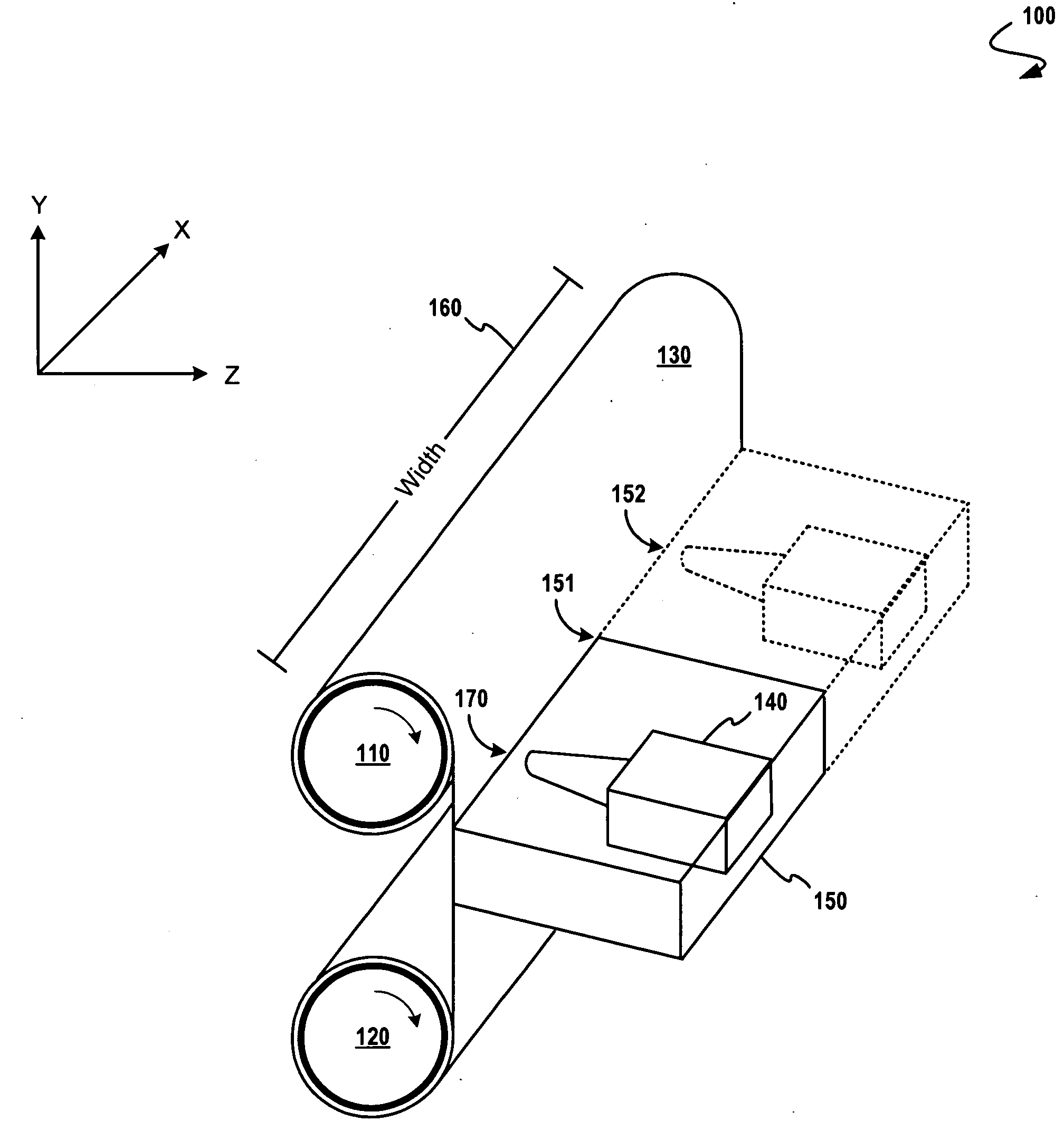
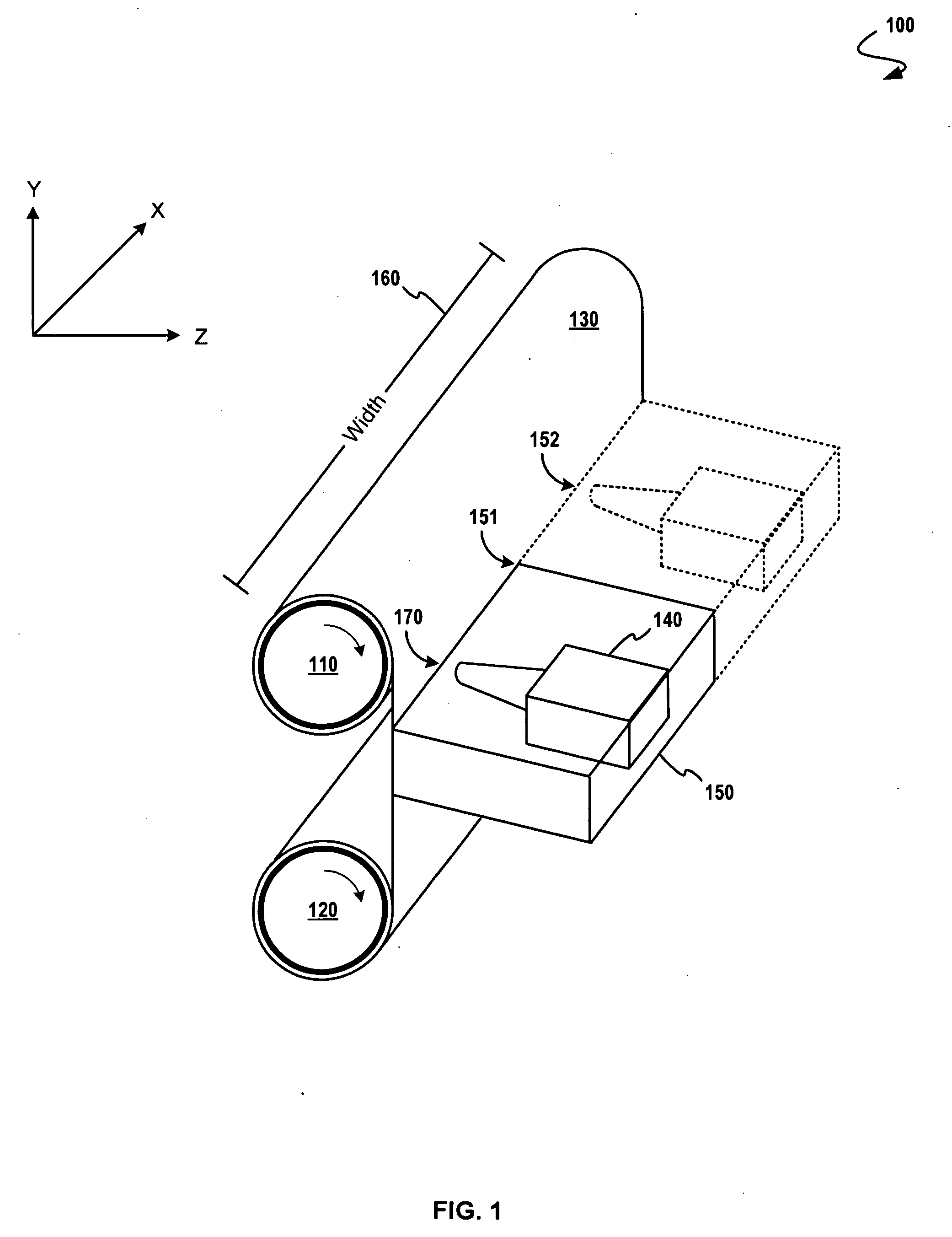
[0024]The embodiments herein generally relate to ellipsometric measurements taken on fibers, which fibers are coated with one or more layers of thin film—the properties of the film being the properties of interest. In some cas...


PUM


Abstract

A method for calibrating an apparatus for ellipsometric measurements performed on an arbitrarily large or continuously moving sample, using a visible sample reference frame, and one or more laser sources in order to calibrate the ellipsometer for variations in the distance between the ellipsometer apparatus and the sample of interest. Included are techniques for projecting a first laser beam spot from an incident laser source onto a sample, then analyzing the position of the first laser beam spot relative to the center of the sample reference frame using human-aided measurements and confirmations and/or computer vision techniques. Then adjusting pivot points and/or apparatus-to-sample distance to achieve a first beam spot being located about the center of the sample reference frame, and concurrently intersecting the plane of the sample. Other techniques include changing the incidence and reflectance angle using a semi-circular track arc design with a stepping motor activating each goniometer arm.

Description

FIELD OF THE INVENTION[0001]The present invention is directed towards ellipsometry, particularly as it relates to ellipsometry measurements performed on coated fibers in the form of fabric or tows.BACKGROUND OF THE INVENTION[0002]Ellipsometry is a versatile and powerful optical technique for the investigation of the physical properties of materials (e.g. a complex refractive index or dielectric function), including properties of thin films. Ellipsometry techniques can yield extremely accurate measurements, and certain ellipsometric measurement techniques provide unequaled capabilities for thin film metrology.[0003]In contrast to ellipsometry, other measurement techniques (e.g. scanning electron microscopy, auger electron spectroscopy, transmission electron microscopy, X-ray photoemission spectroscopy, etc), while quite accurate, tend to require long set-up times, involved sample preparation, challenging (e.g. vacuum) environmental conditions, and are destructive to the sample. Spect...

Claims


Application Information

Patent Timeline
Patent Type & Authority Applications(United States)
IPC IPC(8): G06F19/00G01B11/14G01J4/00
CPCG01B11/0641G01N21/211
Inventor GAO, CHAO
Owner THE UNITED STATES OF AMERICA AS REPRESENTED BY THE SECRETARY OF THE NAVY
Why Eureka
Try Eureka